Download
1 / 4
40 likes | 50 Vues
ER Publication,<br> IJETR, IJMCTR,<br> Journals,<br> International Journals,<br> High Impact Journals, <br>Monthly Journal, <br>Good quality Journals,<br> Research, <br>Research Papers,<br> Research Article, <br>Free Journals, Open access Journals, <br>erpublication.org,<br> Engineering Journal,<br> Science Journals,

E N D
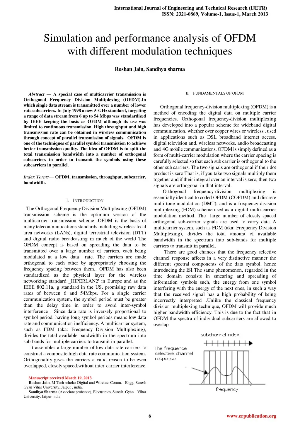
International Journal of Engineering and Technical Research (IJETR) ISSN: 2321-0869, Volume-1, Issue-1, March 2013 Simulation and performance analysis of OFDM with different modulation techniques Roshan Jain, Sandhya sharma II.FUNDAMENTALSOFOFDM Abstract — A special case of multicarrier transmission is Orthogonal Frequency Division Multiplexing (OFDM).In which single data stream is transmitted over a number of lower rate subcarriers. In July 1998 a new 5-GHz standard, targeting a range of data stream from 6 up to 54 Mbps was standardized by IEEE keeping the basis as OFDM although its use was limited to continuous transmission. High throughput and high transmission rate can be obtained in wireless communication through concept of parallel transmission of signals. OFDM is one of the techniques of parallel symbol transmission to achieve better transmission quality. The idea of OFDM is to split the total transmission bandwidth into a number of orthogonal subcarriers in order to transmit the symbols using these subcarriers in parallel. Index Terms—OFDM, transmission, throughput, subcarrier, bandwidth. Orthogonal frequency-division multiplexing (OFDM) is a method of encoding the digital data on multiple carrier frequencies. Orthogonal frequency-division multiplexing has developed into a popular scheme for wideband digital communication, whether over copper wires or wireless , used in applications such as DSL broadband internet access, digital television and, wireless networks, audio broadcasting and 4G mobile communications. OFDM is simply defined as a form of multi-carrier modulation where the carrier spacing is carefully selected so that each sub carrier is orthogonal to the other sub carriers. The two signals are orthogonal if their dot product is zero That is, if you take two signals multiply them together and if their integral over an interval is zero, then two signals are orthogonal in that interval. Orthogonal frequency-division essentially identical to coded OFDM (COFDM) and discrete multi-tone modulation (DMT), and is a frequency-division multiplexing (FDM) scheme used as a digital multi-carrier modulation method. The large number of closely spaced orthogonal sub-carrier signals are used to carry data A multicarrier system, such as FDM (aka: Frequency Division Multiplexing), divides the total amount of available bandwidth in the spectrum into sub-bands for multiple carriers to transmit in parallel. There are good chances that the frequency selective channel response affects in a very distinctive manner the different spectral components of the data symbol, hence introducing the ISI The same phenomenon, regarded in the time domain consists in smearing and spreading of information symbols such, the energy from one symbol interfering with the energy of the next ones, in such a way that the received signal has a high probability of being incorrectly interpreted .Unlike the classical frequency division multiplexing technique, OFDM will provide much higher bandwidth efficiency. This is due to the fact that in OFDM the spectra of individual subcarriers are allowed to overlap multiplexing is I.INTRODUCTION The Orthogonal Frequency Division Multiplexing (OFDM) transmission scheme is the optimum version of the multicarrier transmission scheme .OFDM is the basis of many telecommunications standards including wireless local area networks (LANs), digital terrestrial television (DTT) and digital radio broadcasting in much of the world The OFDM concept is based on spreading the data to be transmitted over a large number of carriers, each being modulated at a low data rate. The carriers are made orthogonal to each other by appropriately choosing the frequency spacing between them.. OFDM has also been standardized as the physical layer for the wireless networking standard ‗HIPERLAN2' in Europe and as the IEEE 802.11a, g standard in the US, promising raw data rates of between 6 and 54Mbps. For a single carrier communication system, the symbol period must be greater than the delay time in order to avoid inter-symbol interference . Since data rate is inversely proportional to symbol period, having long symbol periods means low data rate and communication inefficiency. A multicarrier system, such as FDM (aka: Frequency Division Multiplexing), divides the total available bandwidth in the spectrum into sub-bands for multiple carriers to transmit in parallel. It assembles a large number of low data rate carriers to construct a composite high data rate communication system. Orthogonality gives the carriers a valid reason to be even overlapped, closely spaced,without inter-carrier interference. Manuscript received March 19, 2013 Roshan Jain, M Tech scholar Digital and Wireless Comm. Engg, Suresh Gyan Vihar University, Jaipur , india. Sandhya Sharma (Associate professor), Electronics, Suresh Gyan Vihar University, Jaipur india 6 www.erpublication.org
Simulation and performance analysis of OFDM with different modulation techniques OFDM uses the spectrum much more efficiently by spacing the channels much closer together. This is achieved by making all the carriers orthogonal to one another, preventing interference between the closely spaced carriers Figure 3: Parameter Mapping from Time to Frequency for DFT C. Simulations of OFDM Demodulated data is compared to the original baseband data to find the total number of errors. Dividing the total number of errors by total number of demodulated symbols, the bit- error-rate (BER) is found. Appendix B shows a trial of the OFDM Simulation with the configuration shown in Table I. Figure 2: Concept of OFDM signal: Orthogonal multicarrier technique versus conventional Multicarrier technique. Spectrum is used much more efficiently in OFDM by spacing the channels much closer together. This is achieved by making all the carriers orthogonal to one another, preventing interference between the closely spaced carriers. PARAMETERS VALUES SOURCE IMAGE SIZE 800×600 IFFTSIZE 2048 NUMBER OF CARRIERS 1009 III.OFDMOPERATION A. Definition of Orthogonality: PEAK POWER CLIPPING 9 DB SIGNAL TO NOISE RATIO 12 DB Two periodic signals are orthogonal when the integral of their product, over one period, is equal to zero. This is true of certain sinusoids .The carriers of an OFDM are sinusoids that meet this requirement because each one is a multiple of frequency. B. Concept of DFT and FFT MODULATION METHOD QPSK As shown in Table II in appendix B, there's a BER of 0.68% while the percent error in the output image pixels is 1.80%. This is expected when the OFDM symbol size is not the same as word size of the source data. i.e. Modulation method is not 256-PSK. The reason is that a set of four QPSK symbols is mapped to one 8-bit word, and when one or more of the 4 QPSK symbols in a set is decoded incorrectly, the whole 8-bit word is mistranslated, therefore, it counts as all 4 QPSK symbols are errors when considering the pixels percent error. However, in BER calculation, the interest is the accuracy of the Tx and Rx, thus it only counts any of the QPSK symbols that are decoded incorrectly With 1.80% pixel percent error, When the DFT (Discrete Fourier Transform) of a time signal is taken, the frequency domain results are a function of the time sampling period and the number of samples as shown in Figure 3. The fundamental frequency of the DFT is equal to 1/NT (1/total sample time). The IDFT (Inverse Discrete Fourier Transform) performs the opposite operation to the DFT. It takes a signal defined by frequency components and converts them to a time signal. The parameter mapping is the same as for the DFT. 7 www.erpublication.org
International Journal of Engineering and Technical Research (IJETR) ISSN: 2321-0869, Volume-1, Issue-1, March 2013 the noise on the output image is still easily observable, but the information content received is highly usable. This is due to the use of QPSK, in which received phases have 45o of tolerance. By dropping the number of carriers and IFFT size to about half while all other parameters remain the same, the simulation runtime for both the transmitter and receiver don't seem to vary much. This is because the simulation program monitors the total number of symbols to form one frame of data, thus total number of frames did not very much. The runtime measured depends on the number of computer operations, which directly depends on the number of frames of data needed to be modulated and demodulated for a fixed number of symbols per frame. Runtime measurement does not reflect the variance of the efficiency based on varied numbers of carriers. However, it's meaningful to use this measurement in understanding the variance of efficiency based on varied orders of PSK. The runtimes tripled for a simulation with BPSK while other parameters remain the same. A plot in Figure shows that using 16-PSK and 256-PSK also verifies this theory. NUMBER OF CARRIERS 400 PEAK POWER CLIPPING 3 DB SIGNAL TO NOISE RATIO 0 DB Signal to Noise Ratio Comparison Program Runtime Comparison Received Image Pixel Percentage Error Bit Ratio Comparison SNR is inversely proportional to error rates. To demonstrate this in an experiment, a different set of parameters issued, which is shown in Table II. IV.CONCLUSION Since the transmission bandwidth is much larger than the coherence bandwidth of the channel, highly complex equalizers are needed at the receiver for accurately recovering the transmitted information. Multi-carrier techniques can solve this problem significantly. This paper has explored the role of OFDM in the wireless communication and its advantages over single carrier transmission like Multipath delay spread tolerance, immunity to frequency fading channels, Efficient modulation and PARAMETERS VALUES SOURCE IMAGE SIZE 600×900 IFFTSIZE 1024 8 www.erpublication.org
Simulation and performance analysis of OFDM with different modulation techniques REFERENCES demodulation, high transmission bit rate, Chance to cancel any cannel if is affected by fading. [1]G. Hill, M. Faulkner, and J. Singh, "Reducing the peak-to-average power ratio in OFDM by cyclically shifting partial transmit sequences," Electronics Letters, vol. 36, pp. 560-561, Mar 16 2000. [2]Theory of Frequency http://zone.ni.com/devzone/cda/ph/p/id/269 [3]Acosta, Guillermo. ―OFDM Simulation Using MATLAB‖ 2000J. [4]Litwin, Louis and Pugel, Michael. ―The Principles of OFDM‖ 2001 [5]Tran, L.C. and Mertins, A. ―Quasi-Orthogonal Space-Time- [6]Frequency Codes in MB- OFDM UWB‖ 2007 .Understanding an OFDM http://www.dsplog.com/2008/02/03/understanding-an-ofdm-trans mission/ [7]Minimum frequency spacing for having minimum-frequency-spacing-for-having-orthogonal- sinusoidal [8]G. Fay, "Wireless Data Networking," International Journal of Network Management, 8 March 1992, pp. 8-17 [9]ETSI, "Radio Broadcast Systems: Digital Audio Broadcasting (DAB) to mobile, portable and fixed receivers," ETSI final draft ETS 300 401, Nov 1994. [10]William Shieh and Ivan Djordjevic, Orthogonal Frequency Division Multiplexing for Optical Communications (1st edition, 2010) [11]Schulze, Henrik and Christian Luders. Theory and Applications of OFDM and CDMA John Wiley & Sons, Ltd. 2005 [12]Understanding an http://www.dsplog.com/2008/02/03/understanding-an-ofdm-trans mission [13]Orthogonal Frequency Division Multiplexing, U.S. Patent No. 3, 488,4555, filed November 14, 1966, issued Jan. 6, 1970. [14]Marc Engels et al. with Kluwer: "Wireless OFDM Systems, How to make them work," Hardbound, ISBN 1-4020-7116-7 May 2002 , 232 pp) [15]P.G.M. de Bot, B. Le Floch, V. Mignone, and H.D. Schuette. An overview of the modulation and channel coding schemes developed for digital terrestrial television broadcasting within the dTTb project. In Proc. Int. Broadcasting Convention, 1994 pp 569-576, Amsterdam, The Netherlands. [16]J.S.Chow, J,-C.Tu and J.M.Cioffi : ``A Discrete Multitone Transceiver System for HDSL Applications,'' IEEE J. Select. Areas Commun., Vol. 9, pp.895- -908, Aug. 1991 [17]N.Yee, J-P.Linnartz and G.Fettweis : ``Multi-Carrier CDMA in Indoor Wireless Radio Networks,'' Proc. of IEEE PIMRC'93, pp.109-113, Yokohama, Japan, Sept. 1993 [18]K.Fazel : ``Performance of CDMA/OFDM for Mobile Communication System,'' Proc. of IEEE ICUPC'93, pp.975-979, Ottawa, Canada, Oct. 1993. [19]A.E.Jones, T.A.Wilkinson and S.K.Barton:"Block Coding Scheme for Reduction of Peak to Mean Envelop Power Ratio of Multicarrier Transmission Schemes,"Electronics pp.2098-2099, 8th Dec., 1994. [20]H.Sari and I.Jeanclaude : ``An Analysis of Orthogonal Frequency-Division Multiplexing or Mobile Radio Applications,'' Proc. of 1994 IEEE VTC'94, pp.1635- 1639, Stockholm, Sweden, June 1994. Flexibility, Using the cell capacity to the utmost by adaptively using the highest modulation a user can use, this is allowed by the gain added when less carriers are allocated (up to 18dB gain for 23 carrier allocation instead of 1587 carriers), therefore gaining in overall cell capacity, Enables Single Frequency Network coverage, where coverage problem exists and gives excellent coverage etc. There are also some limitations of this technique which can be removed with the help of suitable techniques like OFDM signal has a high Peak to Average Power Ratio (PAPR), It is more sensitive to carrier frequency offset and drift than the single carrier systems due to leakage in DFT, The OFDM signal has a noise like amplitude with a very large dynamic range, therefore it requires RF power amplifiers with a high peak to average power ratio. An OFDM system is successfully simulated using MATLAB major applications of OFDM are VDSLand ADSL broadband access via Power Line Communication (PLC), POTS copper wiring, ITU-T G.hn, a standard which is provides high-speed local area networking over existing home wiring (phone lines power lines, and coaxial cables), the digital radio systems ISDB-TSB, T-DMB and DAB/EUREKA 147, DAB+, Digital Radio Mondale, and HD Radio, DAB: DAB - OFDM forms the basis for the Digital Audio Broadcasting (DAB) standard in the European market. Digital Audio Broadcasting (DAB) using OFDM has been standardized in Europe and is the next step in evolution beyond FM radio broadcasting providing interference free transmission, Some of the challenges in developing this OFDM simulation program were carefully matching steps in modulator and demodulator, keeping track of data format and data size throughout all the processes of the whole simulation, designing an appropriate frame detector for the receiver, and debugging the MATLAB codes. It was noted that for some combinations of OFDM parameters, the simulation may fail for some trials but may succeed for repeated trails with the same parameters. It is because the random noise generated on every trial differs, and trouble may have been caused for the frame detector in the OFDM receiver due to certain random noise. Future work is required to debug this issue and make the frame detector free of error. Other possible future works to enhance this simulation program include adding ability to accept input source data in a word size other than 8-bit, adding an option to use QAM (Quadrature amplitude modulation) instead of M-DPSK as the modulation method. Division Multiplexing: transmission: OFDM transmission: Letters, Vol.30, No.5, V.FUTURE WORK Roshan Jain, M Tech scholar Digital and Wireless Comm. Engg, Suresh Gyan Vihar University, Jaipur , india , B. E. University 2007 batch, four paper in national conference published. As future work, there are the next points: (1) To improve the performance using some techniques. (2) Some extra functions could be added to the system like for example, configure a multiple-output) system, or adding other functions to make more robust the system, like for example adding a puncture or an interleave. (3) Possibility to add some functions to calculate some signal parameters like EVM, BER and PAPR. from Rajasthan MIMO (multiple-input Sandhya Sharma (Associate professor), Electronics, Suresh Gyan Vihar University, Jaipur india, ME (Digital Comm. M.B.M. Engineering College (Rajasthan) in year 2008 (Electronics Engg.) NIT Raipur, Chhattisgarh, (Earlier Engineering College Raipur) in year 1996, one paper in international conference, 10 paper in journal, 3 workshop attended Engg.) , BE Govt. 9 www.erpublication.org