Download
1 / 4
40 likes | 56 Vues
ER Publication,<br> IJETR, IJMCTR,<br> Journals,<br> International Journals,<br> High Impact Journals, <br>Monthly Journal, <br>Good quality Journals,<br> Research, <br>Research Papers,<br> Research Article, <br>Free Journals, Open access Journals, <br>erpublication.org,<br> Engineering Journal,<br> Science Journals,

E N D
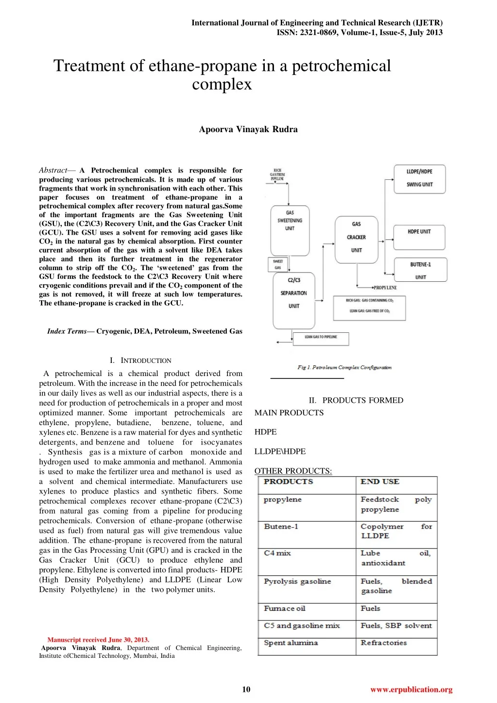
International Journal of Engineering and Technical Research (IJETR) ISSN: 2321-0869, Volume-1, Issue-5, July 2013 Treatment of ethane-propane in a petrochemical complex Apoorva Vinayak Rudra Abstract—APetrochemicalcomplexisresponsiblefor producing various petrochemicals. It is made up of various fragments that work in synchronisation with each other. This paperfocusesontreatmentofethane-propanein a petrochemical complex after recovery from natural gas.Some of the important fragments are the Gas Sweetening Unit (GSU), the (C2\C3) Recovery Unit, and the Gas Cracker Unit (GCU). The GSU uses a solvent for removing acid gases like CO2 in the natural gas by chemical absorption. First counter current absorption of the gas with a solvent like DEA takes place and then its further treatment in the regenerator column to strip off the CO2. The ‘sweetened’ gas from the GSU forms the feedstock to the C2\C3 Recovery Unit where cryogenic conditions prevail and if the CO2 component of the gas is not removed, it will freeze at such low temperatures. The ethane-propane is cracked in the GCU. Index Terms—Cryogenic, DEA, Petroleum, Sweetened Gas I.INTRODUCTION A petrochemical is a chemical product derived from petroleum. With the increase in the need for petrochemicals in our daily lives as well as our industrial aspects, there is a need for production of petrochemicals in a proper and most optimized manner. Some important petrochemicals are ethylene, propylene, butadiene, xylenes etc. Benzene is a raw material for dyes and synthetic detergents, and benzene and toluene for isocyanates . Synthesisgas isa mixture of carbonmonoxide and hydrogen used to make ammonia and methanol. Ammonia is used to make the fertilizer urea and methanol is used as a solvent and chemical intermediate. Manufacturers use xylenes toproduce plastics and synthetic fibers. Some petrochemical complexes recover ethane-propane (C2\C3) from natural gas coming from a pipeline for producing petrochemicals. Conversion of ethane-propane (otherwise used as fuel) from natural gas will give tremendousvalue addition. The ethane-propane is recovered from the natural gas in the Gas Processing Unit (GPU) and is cracked in the Gas Cracker Unit (GCU) to produce ethylene and propylene. Ethylene is converted into final products- HDPE (High Density Polyethylene) and LLDPE (Linear Low Density Polyethylene) in the two polymer units. Fig 1. Petroleum Complex Configuration II.PRODUCTSFORMED MAIN PRODUCTS HDPE LLDPE\HDPE OTHER PRODUCTS: II.PRODUCTS FORMED benzene, toluene, and MAIN PRODUCTS HDPE LLDPE\HDPE OTHER PRODUCTS: Manuscript received June 30, 2013. Apoorva Vinayak Rudra, Department of Chemical Engineering, Institute ofChemical Technology, Mumbai, India 10 www.erpublication.org
Treatment of ethane-propane in a petrochemical complex Wash Column are sent to Rich Amine Flash Drum. The Rich Amine Flash Drum is operated at 6.5 kg /cm2a and 70o C. Most of the hydrocarbons co- absorbed in DEA solution are desorbed in this drum and are routed to the plant fuel gas system. 4. AMINE REGENERATION III.STAGES III.A. GAS PROCESSING UNIT (GPU) There are two important fragments of this unit: • Gas Sweetening Unit (GSU) • C2\C3 Recovery Unit III.A.1 GAS SWEETENING UNIT CO2 present in the feed gas is removed in this by using DEA (Diethanolamine) as a solvent. The unit is designed to handle the feed gas. The term ‘Sweetening’ means removal of acid gases like H2S and CO2 and H2S .This gas forms the feedstock to the C2\C3 Recovery Unit where cryogenicconditions prevail and if the CO2 component of the gasis not removed, it will freeze at such low temperatures.After sweetening, gas is sent to the C2\C3 unit. PROCESS DESCRIPTION 1. ABSORPTION SECTION The raw gas is treated in two parallel high pressure Absorbers. The gas is fed to the Absorber Columns at 52 kg /cm2a and 30o C. This gas is counter-currently treated with DEA solvent (40 wt %) which is fed from the top of the column. The Absorber Column contains30 Valve Trays. around 126o C. The Lean Amine is withdrawn from the bottom of the column and is sent to storage after being cooled to 45o C in Rich / Amine Exchanger and then by cooling water. Vapors from the Regenerator top are condensed in the RegeneratorOverheadCondenser and taken into Regeneration Reflux Drum. The uncondensed gases mainly CO2 (acid gas) arevented to atmosphere at a safe location and thecondensed liquid is pumped back as reflux to the column. 5. AMINE STORAGE The lean amine from Regenerator is sent to Amine Storage Tank fromwhere it is pumped to the Absorbers. The Amine Storage Tank is blanketed with Nitrogen to prevent solvent degradation with Oxygen. 6. AMINE FILTRATION A stream of stored amine solution is continuously sent to the filtration package by amine filtration pump. DEA solvent filtration is required to remove all the dissolved hydrocarbons, scales & solvent degradation products that can cause corrosion and foaming. Thereare basically three levels of filtration: • Activated Carbon Filter which removes corrosion products & Hydrocarbons. •Cartridge filter which removes any Carbon Particles. •Pre‐ coat Filter consisting of cellulose. 7. AMINE DRAIN RECOVERY All the solvents are recovered in an underground Amine Sump Drum. The solvent recovered in this drum is recycled to the Solvent Circuit by a submergedpump. 2TREATED GAS WATER WASH AND C COOLING The treated gas from the Absorber Column is counter – currently washed with water in Water W ash Column equipped with pall rings to remove the DEA carriedover with the gas. The DEA solution in solution inwater is removed from the bottom of this column and sent to the Rich Amine Flash Drum. The treated gas iscooled to 40o C and leaves the Unit at 50 kg /cm2a. Fig 2. Block diagram of Gas Sweetening Unit 3. RICH AMINE CIRCUIT The rich amine from the Absorber bottom and the Water 11 www.erpublication.org
International Journal of Engineering and Technical Research (IJETR) ISSN: 2321-0869, Volume-1, Issue-5, July 2013 Dryers. 3. FEED GAS CHILLING / SEPARATION After drying the feed gas is taken to the Demathaniser Bottom Reboiler where it is further cooled to around 5oC to 7o C after supplying the Column Reboiler duty. The Feed Gas then enters the Feed Gas Chiller #1 where it is cooled down to – 32o C by the Separator 1 and 2 liquids and the Lean Gas. The gas is further chilled down to – 38o C in the Demathaniser Side Reboiler. The Gas is chilled in the Feed Gas Chiller 1 to about –55o C to – 60o C. This partially condensed Feed Gas at this stage is taken to the Separator 1 where the condensed liquid is separated and sent to Chiller 1 for Cold Recovery. This liquid is thenfed to the Demathaniser Column. The uncondensed vapors from the Separator 1 are cooled to – 68o C by the outgoing Lean Gas in the FeedGas Chiller 2. These vapors are now taken to Separator 2 where again the condensed liquid is separated. Cold from this liquid is recovered in Feed Gas Chiller 1. It is then mixed with the Separator 1 liquid and this is fed to he Demathaniser Column on Tray 18. The Overhead gas fromSeparator 2 is expanded isoentropically in the Feed Gas Expander to around 22 kg /cm2a and the temperature of the gas drops to 98o C. Dueto this chilling, there is further condensation of the gas.This Vapor Liquid mixture is fed to the DemathaniserColumn on the 8th tray. The work available from theisoentropic expansion of the Separator 2 vapor is used to compress the feed gas 5. FRACTIONATION This section consists of a Demathaniser Column which serves to recover C2-C3 product from I.Separator 1 and 2 liquids received at -68o C II. Feed Gas Expanderoverheatedvapors received at -98o C. This column separates almost all the Methane from the Gas. It consists of 36 valve trays and one chimney tray for supplying feed toSideReboiler. The Column Reboilers chill down the Feed Gas and in turn recover reboiler duty. The Overhead vapors are chilled from – 98o C to – 102o C and condensed in the DemathaniserOverheadCondenser by the cold gas from the Demathaniser Overhead Expander outlet (-117o C). The Demathaniser overhead vapor is expanded from 21.5 kg /cm2a and due to this the gas is chilled to – 117o C. This cold Methane isthe major source of refrigeration in the unit. The bottom product from the Demathaniser Column is the C2-C3 product, which is pumped as feed to Cracker Unit or sent to Storage. The recovery of C2 is around 90%. 6. LEAN GAS COMPRESSION The lean gas after giving away its cold to a series of Fig 2. Block diagram of Gas Sweetening Unit III.A.2 C2/C3 RECOVERY UNIT In the plant, C2/C3 fraction of the feed gas is recovered under cryogenic conditions by Turbo-Expander process. The C2/C3 product from this unit forms the feedstock for the Gas Cracker Unit. The C2/C3 recovered from Natural Gas in this unit is used to produce ethylene. 1. FEED GAS COMPRESSION The Sweetened Gas is received from the Gas Sweetening Unit at 50 kg /cm2a & 40o C. In the Feed Gas Knock Out Drum where the entrapped liquids are removed. The gas is now compressed to 55 kg /cm2a ina Feed Gas Expander Compressor. 2. FEED GAS DRYING / REGENERATION The Compressed gas is cooled down to 37o C using cooling water in Feed Gas Compressor Discharge Cooler and further down to 18o C by the outgoing Lean Gas in the Feed / Lean Gas Exchanger. The condensedmixture from the gas is removed in MoistureSeparator. The gas is now saturated with water that is removed in a Dryer to a Water Dew Point of -100o C using molecular sieves as desiccants. There are two Dryers out of which one is in drying mode and the other is either a standby or in regeneration mode. The drying period is around 12 hours and the regeneration is also 12 hours. A part of the Lean Gas from the first stage discharge of the Lean Gas Compressor is heated to 320o C in a GasFired Heater and this hot gas is used for regenerationof the The Overhead gas from Separator 2 is expanded isoentr opically in the Feed Gas Expander to around 22 kg /cm2a and the 12 www.erpublication.org
Treatment of ethane-propane in a petrochemical complex exchangers get heated to 25o C to 30o C and is first compressed from 10 kg /cm2a to 12 kg /cm2a in the Demathaniser Overhead Expander Compressor is further compressed to 55 kg /cm2a in a 2- stage gas turbine driven Lean Gas Compressors. It is cooled to 40o C and sent back to the pipeline. About 36 Ton/hr of Lean Gas is drawn from first stage discharge of the Lean Gas Compressor for Dryer Regeneration. This gas is then compressed to 55 kg /cm2a in a Steam Turbine driven Residue Gas Compressor and is then sent to the Lean Gas Compressor Discharge Header. 7. C2/C3 STORAGE 8 spheres of 15 m diameter having nominal activity of 1500 m3 are provided in off sites area for storage of C2/C3. Normally 90% of the C2/C3 produced will be supplied directly from the GPU TO GCU as feed. A slip stream of around 10% of C2/C3 will be sent to storage and same quantity of C2/C3 will be pimped back from storage to GCU. In case GPU is not in operation, entire quantity of C2/C3 will be supplied from storage. direct firing of fuel gas in the furnace .This unit can be broadly divided into two sections namely Hot and Cold section. The Hot section comprises of feed vaporization, cracking furnaces, water quench, cracked gas compression, caustic wash and dehydrators. The Cold section comprises of the Demathaniser and the downstream separation facilities. After cracking, ethylene, propylene and other useful products are recovered and sent to various sections for further processing. IV.CONCLUSION This paper proposes a method for the recovery of various petrochemicals (from ethane-propane mixture) which playa vital role in our daily as well as our industrial aspects. In this work, the methods incorporated for the recovery and processing of petrochemicals result in optimization of the available resources with increased benefits. ACKNOWLEDGMENT Sincere thanks to Mr. B.K. Kerketta, Mr.Ajay Asthana and Ms. Singh for their help and tremendous guidance without which the success of this project would not have been possible. III .B. BASIC FUNCTION OF GAS CRACKING UNIT The breaking of a molecule to yield more useful products is called cracking. Cracking requires high temperature to initiate it and is endothermic. This heat is supplied by the 13 www.erpublication.org