Download
1 / 23
240 likes | 543 Vues
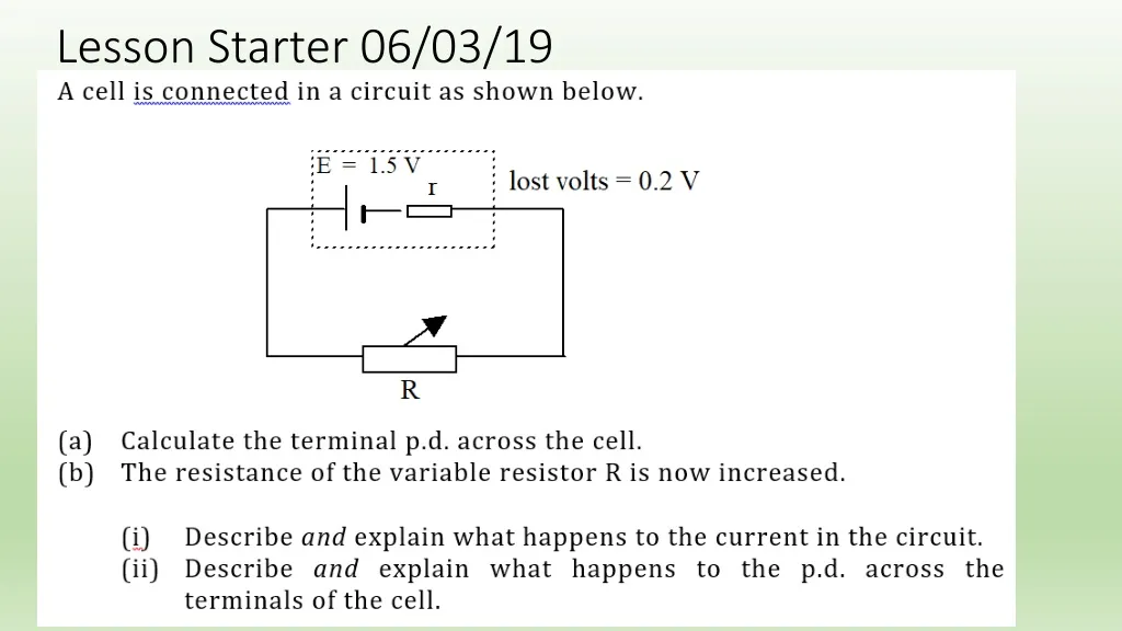
Lesson Starter 06/03/19. To do…. You have 10 minutes to finish drawing your graphs from Monday – this is a skill you need to have for the final exam! Once you have drawn your graph, extend the line of best fit back till it hits the y-axis – this is the emf of the battery.

E N D
To do… • You have 10 minutes to finish drawing your graphs from Monday – this is a skill you need to have for the final exam! • Once you have drawn your graph, extend the line of best fit back till it hits the y-axis – this is the emf of the battery. • Calculate the gradient of the line – this is the negative of the internal resistance. • Y= mx + c Where Y = Vtpd, m = -r, x = I and c = emf
Emf, Internal Resistance and Graphs • From a graph of Vtpd vs I, if you extend the line of best fit back till it hits the y-axis this will be the emfof the battery. • The gradient of the line is the negative of the internal resistance. i.e. -r Y= mx + c Where Y = Vtpd, m = -r, x = I and c = emf i.e. Vtpd = -rI + Emf Emf = Vtpd + Ir IT’S THE FORMULA ON THE RELATIONSHIPS SHEET!! MAGIC!
Load Resistors and Load Matching • The power transferred to the load in the circuit shown is determined by P = V2/R, where V is the t.p.d. • The optimum value of power transfer occurs when the value for R is equal tothe internal resistance, r. This is known as load matching.
Load Matching • However, load matching produces very inefficient circuits with 50% of the power dissipated inside the source. To produce maximum efficiency the load resistance should be much greater than the internal resistance. i.e. R > r
CfE Higher Physics Unit 1 Electricity Capacitors
Capacitors A capacitor consists of two metal plates separated by an insulator. A capacitor has the following symbol: A capacitor can store electrical charge – not energy! The charge that can be stored is directly proportional to the potential difference between the plates.
Q C = V charge capacitance = voltage Capacitance The capacitance of a capacitor is defined as the ratio of charge to potential difference. The SI unit of capacitance is the farad, F. A capacitor of one farad stores one coulomb of charge for each volt of potential difference applied across it. The symbol for capacitance is C. 1F = 1 C V-1
A B C V Measuring Capacitance The capacitance of a capacitor can be measured using the following circuit: The capacitor is charged by setting the switch to position A, then discharged through the coulombmeter by moving the switch to position B. Pairs of readings of potential difference and charge are taken.
Charge(C) p.d. (V) 0 Measuring Capacitance(continued) A graph of charge against potential difference is drawn: Learn this graph! The capacitance of the capacitor is equal to the gradient of the graph.
Q 4 x 10⁻³ C = = V 5 Worked Example Calculate the capacitance of a capacitor which stores 4 mC of charge when a potential difference of 5 V is applied across it. = 0.8 mF = 8 x 10⁻⁴ F
Energy = area under graph charge Q p.d. 0 V Capacitors and Energy When a capacitor is charged work is done in moving charge on and off the capacitor’s plates. This energy is stored in the capacitor. The energy stored in a capacitor is equal to the area under the charge-potential difference graph for the capacitor. E = ½ QV
Q2 E = ½ C Capacitors and Energy(continued) Since Q = CV the following equations can be obtained for the energy stored in a capacitor: E = ½ QV E = ½ CV2 Substituting for Q: Substituting for V:
Worked Example Calculate the energy stored in a 220 nF capacitor when it is charged up to 24 V. E = ½ CV2 = ½ x (220 x 10-9) x 242 = 6.34 x 10⁻⁵ J = 63.4 mJ
C Vs R Vs Imax = R 0 0 Charging Capacitors When a capacitor is charged through a resistor it takes time for it to become fully charged. Voltage across capacitor Current through capacitor Vs Learn these graphs!
C R Vs - Imax = R Discharging Capacitors When a capacitor is discharged through a resistor it takes time for it to become fully discharged. Voltage across capacitor Current through capacitor 0 Vs 0 Learn these graphs!
Effect of Capacitance If the value of the capacitor is increased it takes longer to charge. Voltage across capacitor Current through capacitor 0 0 Learn the effect!
Effect of Resistance If the value of the resistor is increased it takes longer to charge. Voltage across capacitor Current through capacitor 0 0 Learn the effect!
current (A) frequency (Hz) 0 Resistors in a.c. Circuits The current through a resistor is not affected by the frequency of the a.c. supply. Learn the effect and graph!
current (A) 0 frequency (Hz) Capacitors in a.c. Circuits The current through a capacitor is directly proportional to the frequency of the a.c. supply. Learn the effect and graph!
A V Capacitors in a.c. Circuits(continued) This relationship can be proved by setting up the following circuit: • Readings of current are taken for a range of different frequencies from the signal generator. • For each reading the voltage is kept constant by monitoring the voltmeter and adjusting the output amplitude of the signal generator. • A graph of current against frequency can then be drawn. This gives a best fit straight line through the origin.
Uses of Capacitors Camera flash: A capacitor stores energy which can be released when in a sudden burst when required. Smoothing: A capacitor can be used to smooth the pulses of a rectified a.c. power supply to produce a d.c. voltage. Loudspeakers: Since capacitors allow high frequencies to pass through them them they can be used to route high frequencies through ‘tweeter’ speakers and low frequencies through ‘woofers’. Blocking d.c.: Capacitors can be used to block the d.c. component of electrical signals, but allow the a.c. component to pass (e.g. in an oscilloscope).