Download
1 / 68
680 likes | 942 Vues
Chapter 4 Energy Analysis of Closed Systems Study Guide in PowerPoint to accompany Thermodynamics: An Engineering Approach , 7th edition by Yunus A. Çengel and Michael A. Boles.

E N D
Chapter 4Energy Analysis of Closed SystemsStudy Guide in PowerPointto accompanyThermodynamics: An Engineering Approach, 7th editionby Yunus A. Çengel and Michael A. Boles
For more information and animations illustrating this topic visit the Animation Library developed by Professor S. Bhattacharjee, San Diego State University, at this link. test.sdsu.edu/testhome/vtAnimations/index.html The first law of thermodynamics is an expression of the conservation of energy principle. Energy can cross the boundaries of a closed system in the form of heat or work. Heat is energy transfer across a system boundary due solely to the temperature difference between a system and its surroundings. Work energy can be thought of as the energy expended to lift a weight. Chapter 4
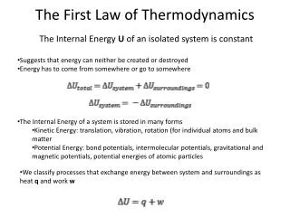
Closed System First Law A closed system moving relative to a reference plane is shown below where z is the elevation of the center of mass above the reference plane and is the velocity of the center of mass. Closed System Heat Work z Reference Plane, z = 0 For the closed system shown above, the conservation of energy principle or the first law of thermodynamics is expressed as Chapter 4
or According to classical thermodynamics, we consider the energy added to be net heat transfer to the closed system and the energy leaving the closed system to be net work done by the closed system. So Where Normally the stored energy, or total energy, of a system is expressed as the sum of three separate energies. The total energy of the system, Esystem, is given as Chapter 4
Recall that U is the sum of the energy contained within the molecules of the system other than the kinetic and potential energies of the system as a whole and is called the internal energy. The internal energy U is dependent on the state of the system and the mass of the system. For a system moving relative to a reference plane, the kinetic energy KE and the potential energy PE are given by The change in stored energy for the system is Now the conservation of energy principle, or the first law of thermodynamics for closed systems, is written as Chapter 4
If the system does not move with a velocity and has no change in elevation, the conservation of energy equation reduces to We will find that this is the most commonly used form of the first law. Closed System First Law for a Cycle Since a thermodynamic cycle is composed of processes that cause the working fluid to undergo a series of state changes through a series of processes such that the final and initial states are identical, the change in internal energy of the working fluid is zero for whole numbers of cycles. The first law for a closed system operating in a thermodynamic cycle becomes Chapter 4
Example 4-1 Complete the table given below for a closed system under going a cycle. Process Qnet kJ Wnet kJ U2 – U1 kJ 1-2 +5 -5 2-3 +20 +10 3-1 -5 Cycle Chapter 4
(Answer to above problem) Row 1: +10, Row 2: +10, Row 3: -10, -5 Row 4: +15, +15, 0 In the next section we will look at boundary work in detail. Review the text material on other types of work such as shaft work, spring work, electrical work. Chapter 4
Closed system boundary work The piston-cylinders of the internal combustion engine shown below may be considered to operate as a closed system when the intake and exhaust valves are closed. This internal combustion engine is an eight piston-cylinder device. Chapter 4
Boundary Work Work is energy expended when a force acts through a displacement. Boundary work occurs because the mass of the substance contained within the system boundary causes a force, the pressure times the surface area, to act on the boundary surface and make it move. This is what happens when products of combustion, the “gas” in the figure below, of an internal combustion engine contained in a piston-cylinder device expands against the piston and forces the piston to move; thus, boundary work is done by the gas on the piston. Note the “gas” could also be a real fluid such as steam of refrigerant-134a. Chapter 4
Boundary work is then calculated from Since the work is process dependent, the differential of boundary work Wb is called inexact. The above equation for Wb is valid for a quasi-equilibrium process and gives the maximum work done during expansion and the minimum work input during compression. In an expansion process the boundary work must overcome friction, push the atmospheric air out of the way, and rotate a crankshaft. Chapter 4
To calculate the boundary work, the process by which the system changed states must be known. Once the process is determined, the pressure-volume relationship for the process can be obtained and the integral in the boundary work equation can be performed. For each process we need to determine So as we work problems, we will be asking, “What is the pressure-volume relationship for the process?” Remember that this relation is really the force-displacement function for the process. The boundary work is equal to the area under the process curve plotted on the pressure-volume diagram. Chapter 4
Note from the above figure: P is the absolute pressure and is always positive. When dV is positive, Wb is positive. When dV is negative, Wb is negative. Since the areas under different process curves on a P-V diagram are different, the boundary work for each process will be different. The next figure shows that each process gives a different value for the boundary work. Chapter 4
An example of negative classical thermodynamics boundary work is the work required to drive a compressor. The figure below shows a 7.5 horse power, two stage (two pistons) compressor with intercooling attached to an eighty gallon reservoir (see Chapter 7 for a discussion of this device). The calculated boundary work Wnet to compress the gas will be negative because the pistons do work on the air. Of course, the actual work supplied by the motor Win is negative of the calculated work.
P 1 2 V P-V diagram for V = constant Some Typical Processes Constant volume process If the volume is held constant, dV = 0, and the boundary work equation becomes If the working fluid is an ideal gas, what will happen to the temperature of the gas during this constant volume process? Chapter 4
P 2 1 V P-V DIAGRAM for P = CONSTANT Constant pressure process If the pressure is held constant, the boundary work equation becomes For the constant pressure process shown above, is the boundary work positive or negative and why? Chapter 4
Constant temperature process, ideal gas If the temperature of an ideal gas system is held constant, then the equation of state provides the pressure-volume relation Then, the boundary work is Note: The above equation is the result of applying the ideal gas assumption for the equation of state. For real gases undergoing an isothermal (constant temperature) process, the integral in the boundary work equation would be done numerically. Chapter 4
The polytropic process The polytropic process is one in which the pressure-volume relation is given as The exponent n may have any value from minus infinity to plus infinity depending on the process. Some of the more common values are given below. Process Exponent n Constant pressure 0 Constant volume Isothermal & ideal gas 1 Adiabatic & ideal gas k = CP/CV Here, k is the ratio of the specific heat at constant pressure CP to specific heat at constant volume CV. The specific heats will be discussed later. Chapter 4
The boundary work done during the polytropic process is found by substituting the pressure-volume relation into the boundary work equation. The result is Note: for the polytropic process the constant, Const = P1V1 = P2V2 Notice that the result we obtained for an ideal gas undergoing a polytropic process when n = 1 is identical to that for an ideal gas undergoing the isothermal process. Chapter 4
System Boundary Nitrogen gas Wb 2 P Example 4-2 Three kilograms of nitrogen gas at 27C and 0.15 MPa are compressed isothermally to 0.3 MPa in a piston-cylinder device. Determine the minimum work of compression, in kJ. System: Nitrogen contained in a colsed, piston-cylinder device. Process: Constant temperature 1 V P-V DIAGRAM for T = CONSTANT Chapter 4
Property Relation: Check the reduced temperature and pressure for nitrogen. The critical state properties are found in Table A-1. Since PR<<1 and T>2Tcr, nitrogen is an ideal gas, and we use the ideal gas equation of state as the property relation. Chapter 4
Work Calculation: For an ideal gas in a closed system (mass = constant), we have Since the R's cancel, we obtain the combined ideal gas equation. Since T2 = T1, Chapter 4
The net work is On a per unit mass basis The net work is negative because work is done on the system during the compression process. Thus, the work done on the system is 184.5 kJ, or 184.5 kJ of work energy is required to compress the nitrogen. Chapter 4
System Boundary for water Wb Heat Example 4-3 Water is placed in a piston-cylinder device at 20 C, 0.1 MPa. Weights are placed on the piston to maintain a constant force on the water as it is heated to 400 C. How much work does the water do on the piston? System: The water contained in the piston-cylinder device Property Relation: Steam tables Process: Constant pressure Chapter 4
Work Calculation: Since there is no Wother mentioned in the problem, the net work is Since the mass of the water is unknown, we calculate the work per unit mass. Chapter 4
At T1 = 20C, Psat = 2.339 kPa. Since P1 > 2.339 kPa, state 1 is compressed liquid. Thus, v1vf at 20 C = 0.001002 m3/ kg At P2 = P1 = 0.1 MPa, T2 > Tsat at 0.1 MPa = 99.61C. So, state 2 is superheated. Using the superheated tables at 0.1 MPa, 400C v2 = 3.1027 m3/kg The water does work on the piston in the amount of 310.2 kJ/kg. Chapter 4
Example 4-4 One kilogram of water is contained in a piston-cylinder device at 100 C. The piston rests on lower stops such that the volume occupied by the water is 0.835 m3. The cylinder is fitted with an upper set of stops. When the piston rests against the upper stops, the volume enclosed by the piston-cylinder device is 0.841 m3. A pressure of 200 kPa is required to support the piston. Heat is added to the water until the water exists as a saturated vapor. How much work does the water do on the piston? System: The water contained in the piston-cylinder device P Stops System Boundary Stops Wb Wb Water v Chapter 4
Property Relation: Steam tables Process: Combination of constant volume and constant pressure processes to be shown on the P-v diagram with respect to the saturation lines as the problem is solved. Work Calculation: The specific volume at state 1 is At T1 = 100C, Therefore, vf < v1 < vg and state 1 is in the saturation region; so P1 = 101.35 kPa. Show this state on the P-v diagram. Now let’s consider the processes for the water to reach the final state. Process 1-2: The volume stays constant until the pressure increases to 200 kPa. Then the piston will move. Chapter 4
Process 2-3: Piston lifts off the bottom stops while the pressure stays constant. Does the piston hit the upper stops before or after reaching the saturated vapor state? Let's set At P3 = P2 = 200 kPa Thus, vf < v3 < vg. So, the piston hits the upper stops before the water reaches the saturated vapor state. Now we have to consider a third process. Process 3-4: With the piston against the upper stops, the volume remains constant during the final heating to the saturated vapor state and the pressure increases. Because the volume is constant in process 3-to-4, v4 = v3 = 0.841 m3/kg and v4 is a saturated vapor state. Interpolating in either the saturation pressure table or saturation temperature table at v4 = vg gives Chapter 4
The net work for the heating process is (the “other” work is zero) Later in Chapter 4, we will apply the conservation of energy, or the first law of thermodynamics, to this process to determine the amount of heat transfer required. Chapter 4
P 1 2 System Boundary Wb Air V Example 4-5 Air undergoes a constant pressure cooling process in which the temperature decreases by 100C. What is the magnitude and direction of the work for this process? System: Chapter 4
Property Relation: Ideal gas law, Pv = RT Process: Constant pressure Work Calculation: Neglecting the “other” work The work per unit mass is The work done on the air is 28.7 kJ/kg. Chapter 4
Example 4-6 Find the required heat transfer to the water in Example 4-4. Review the solution procedure of Example 4-4 and then apply the first law to the process. Conservation of Energy: In Example 4-4 we found that The heat transfer is obtained from the first law as where Chapter 4
At state 1, T1 = 100C, v1 = 0.835 m3/kg and vf < v1 < vg at T1. The quality at state 1 is Chapter 4
Because state 4 is a saturated vapor state and v4 = 0.841 m3/kg, interpolating in either the saturation pressure table or saturation temperature table at v4 = vg gives Now The heat transfer is Heat in the amount of 1072.42 kJ is added to the water. Chapter 4
Specific Heats and Changes in Internal Energy and Enthalpy for Ideal Gases Before the first law of thermodynamics can be applied to systems, ways to calculate the change in internal energy of the substance enclosed by the system boundary must be determined. For real substances like water, the property tables are used to find the internal energy change. For ideal gases the internal energy is found by knowing the specific heats. Physics defines the amount of energy needed to raise the temperature of a unit of mass of a substance one degree as the specific heat at constant volume CV for a constant-volume process, and the specific heat at constant pressure CP for a constant-pressure process. Recall that enthalpy h is the sum of the internal energy u and the pressure-volume product Pv. Chapter 4
In thermodynamics, the specific heats are defined as Simple Substance The thermodynamic state of a simple, homogeneous substance is specified by giving any two independent, intensive properties. Let's consider the internal energy to be a function of T and v and the enthalpy to be a function of T and P as follows: The total differential of u is Chapter 4
The total differential of h is Using thermodynamic relation theory, we could evaluate the remaining partial derivatives of u and h in terms of functions of P,v, and T. These functions depend upon the equation of state for the substance. Given the specific heat data and the equation of state for the substance, we can develop the property tables such as the steam tables. Ideal Gases For ideal gases, we use the thermodynamic function theory of Chapter 12 and the equation of state (Pv = RT) to show that u, h, CV, and CP are functions of temperature alone. For example when total differential for u = u(T,v) is written as above, the function theory of Chapter 12 shows that Chapter 4
Let’s evaluate the following partial derivative for an ideal gas. For ideal gases Chapter 4
This result helps to show that the internal energy of an ideal gas does not depend upon specific volume. To completely show that internal energy of an ideal gas is independent of specific volume, we need to show that the specific heats of ideal gases are functions of temperature only. We will do this later in Chapter 12. A similar result that applies to the enthalpy function for ideal gases can be reviewed in Chapter 12. Then for ideal gases, The ideal gas specific heats are written in terms of ordinary differentials as Chapter 4
Vibration mode Rotation mode “Dumbbell model” Translation mode T Using the simple “dumbbell model” for diatomic ideal gases, statistical thermodynamics predicts the molar specific heat at constant pressure as a function of temperature to look like the following The following figure shows how the molar specific heats vary with temperature for selected ideal gases. Read more about specific heats at http://www.iun.edu/~cpanhd/C101webnotes/matter-and-energy/specificheat.html Chapter 4
The differential changes in internal energy and enthalpy for ideal gases become The change in internal energy and enthalpy of ideal gases can be expressed as Chapter 4
2a P 2b 2c 1 T2 T1 V P-V diagram for several processes for an ideal gas. where CV,ave and CP,ave are average or constant values of the specific heats over the temperature range. We will drop the ave subscript shortly. In the above figure an ideal gas undergoes three different process between the same two temperatures. Process 1-2a: Constant volume Process 1-2b: P = a + bV, a linear relationship Process 1-2c: Constant pressure These ideal gas processes have the same change in internal energy and enthalpy because the processes occur between the same temperature limits. Chapter 4
To find u and h we often use average, or constant, values of the specific heats. Some ways to determine these values are as follows: 1.The best average value (the one that gives the exact results) See Table A-2(c) for variable specific data. 2.Good average values are and Chapter 4
3.Sometimes adequate (and most often used) values are the ones evaluated at 300 K and are given in Table A-2(a). Let's take a second look at the definition of u and h for ideal gases. Just consider the enthalpy for now. Let's perform the integral relative to a reference state where h = href at T = Tref. At any temperature, we can calculate the enthalpy relative to the reference state as Chapter 4
A similar result is found for the change in internal energy. These last two relations form the basis of the air tables (Table A-17 on a mass basis) and the other ideal gas tables (Tables A-18 through A-25 on a mole basis). When you review Table A-17, you will find h and u as functions of T in K. Since the parameters Pr, vr, and so, also found in Table A=17, apply to air only in a particular process, call isentropic, you should ignore these parameters until we study Chapter 7. The reference state for these tables is defined as A partial listing of data similar to that found in Table A.17 is shown in the following figure. Chapter 4
In the analysis to follow, the “ave” notation is dropped. In most applications for ideal gases, the values of the specific heats at 300 K given in Table A-2 are adequate constants. Exercise Determine the average specific heat for air at 305 K. Chapter 4 (Answer: 1.005 kJ/kgK, approximate the derivative of h with respect to T as differences)
Relation between CP and CV for Ideal Gases Using the definition of enthalpy (h = u + Pv) and writing the differential of enthalpy, the relationship between the specific heats for ideal gases is where R is the particular gas constant. The specific heat ratio k (fluids texts often use instead of k) is defined as Extra Problem Show that Chapter 4
Example 2-9 Two kilograms of air are heated from 300 to 500 K. Find the change in enthalpy by assuming a. Empirical specific heat data from Table A-2(c). b. Air tables from Table A-17. c. Specific heat at the average temperature from Table A-2(c). d. Use the 300 K value for the specific heat from Table A-2(a). a.Table A-2(c) gives the molar specific heat at constant pressure for air as The enthalpy change per unit mole is Chapter 4