Download
1 / 52
530 likes | 1.03k Vues
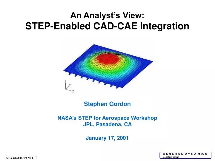
An Analyst’s View: STEP-Enabled CAD-CAE Integration Stephen Gordon NASA’s STEP for Aerospace Workshop JPL, Pasadena, CA January 17, 2001. Outline of Topics. CAD-CAE Integration Domains Purpose, Scope, and Scale of Analysis CAD-Centric vs. CAE-Centric Processes

E N D
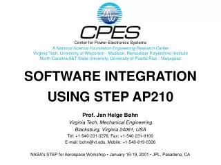
An Analyst’s View: STEP-Enabled CAD-CAE Integration Stephen Gordon NASA’s STEP for Aerospace Workshop JPL, Pasadena, CA January 17, 2001
Outline of Topics CAD-CAE Integration Domains Purpose, Scope, and Scale of Analysis CAD-Centric vs. CAE-Centric Processes Categories of Integration (What is truly ‘Seamless’?) De-Featuring Geometry (Content, Amount of Detail) Geometry ‘Gender Changing’ Needs and Tools “Simulation-Specific Geometry” vs. CAD Geometry Collaboration (Inter- and Intra-Company) ISO STEP 10303 is not just about Data Exchange AP209 is an Enabler for CAD-CAE Integration AP209 = CAD + CAE + FEM + FEA + PDM (Mnemonic) Backup Slides
CAE Functionality Computer-Aided Engineering (CAE) is made up of many varied and diverse functions, depending upon one’s organization and it’s structure. My focus will be on the exchange and sharing of design and engineering data (largely geometry and material information) for use in computational analysis tools, specifically finite element method codes. My purpose today is to define where I see, as an analyst, the potential and growing use for ISO STEP AP209. There is no attempt to slight many other important (non-analytical) engineering functions in the CAD-CAE domain related to the overall design, approval, and life-cycle of the products we create.
CAD and CAEIntegration The key to understanding CAD-CAE Integration, is related to the scale, scope and purpose of the required engineering analysis - e.g. Finite Element Analysis (FEA). It is not simply related to the existence of captured CAD geometry, a perception unwittingly left during product model ‘walk-throughs’. The closer the scale, scope and purpose of an engineering analysis is to the type and detail of the existing CAD product model geometry, the greater the likelihood that a closely-coupled, automated, or even seamless integrated CAD-CAE process can be implemented.
Scope, Purpose, and Scale Small-scale, single part optimization “Widgets & Gadgets” Large-scale simulation, e.g. vehicle crash-worthiness These may both employ the same software, but with significantly different models!
Large-Scale Simulation, Full Vehicle Models Part of the CAE Domain Such analyses and simulations likely include multi-physics and media-structure interaction
CAD and CAEIntegration When the scale, scope and purpose of an engineering analysis are not consistent with the type and detail of the existing CAD product model geometry, a computer-assisted “man-in-the-loop” or semi-automated process may be more feasible and appropriate than a fully-automated process. (Still a place for engineering judgement.) We have found that the time and cost to change, re-work, and de-feature CAD geometry can sometimes be greater than that for creating analysis models from readily-generated “idealized” geometry. (Not a popular view in today’s world!) The more abstract, idealized geometry used for analysis is also referred to as “Simulation-Specific” or “FEA-Specific Geometry”.
Analysis Model Creation (e.g. FEA) Geometry is not always the same! Change Type or “Gender” Derived Idealized Geometry Engr. Anal. Model (FEM) Captured CAD Geometry Simplify Idealize De-Feature Pave Mesh Discretize A mechanical engineer, a structural engineer, and a piping engineer may each require different forms of geometry capture.
Geometry Representation 1D Line (Curve) Same Object ... 2D Surface (Shell) Multiple/Different Forms of Geometry Capture 3D Solid (Volume)
Exploded View - Same Geometry, Different Data Capture 1D Line (Curve) 2D Surface (Shell) 3D Solid (Volume) “Gender Changing”
Integrated CAD-CAEProcess The value of engineering analysis and optimization early (‘up front’) in the design process is now readily accepted and is generally unassailable. Unfortunately, there is often the perception (sometimes from MCAD vendor hype) that engineering analysis is a totally seamless process within CAD. This view can be a disservice to many sectors of business, where solid product models have become the CAD approach of choice, but the wrong geometry for analysis. Fortunately, articles in the literature have recently begun to reflect some of these different views on delivering analysis.
Recent Articles Show Enlightened Views “Three-Dimensional CAD Design and Analyzing with Shell Elements - A Soluble Contradiction?”,by M. W. Zehn, H. M. Baumgarten, & P. Wehner, NAFEMS 7th Int’l. Conf., Newport, RI, April 1999 “Don’t Change the Model Till the Simulation Finishes”,by Paul Kurowski, Machine Design, August 19, 1999 “Rookie Mistakes - Over Reliance on CAD Geometry”,by Vince Adams, NAFEMS Benchmark, October 1999 “Common Misconceptions About FEA”,by Vince Adams, ANSYS Solutions, Fall 2000 “Eight Tips for Improving Integration Between CAD and CFD”,by Scott Gilmore, Desktop Engineering, May 2000
“Don’t Change the Model Till the Simulation Finishes” by Paul Kurowski Machine Design August 19, 1999 When analysis geometry is not the same as design geometry! “Simulation-specific geometry”or “FEA-specific geometry”
CAD-CAE Integration • Whether CAD-CAE applications can be closely-integrated and automated depends upon: • The scale, scope, and purpose of the CAE analysis. • The nature and type (order, or “gender”) of the captured CAD geometry. • The amount of detail required for the CAE application. Today’s bottleneck in CAD-CAE integration is not automated mesh (grid) generation, it lies with efficient creation of appropriate simulation-specific geometry.
The First “Problem” - Geometry Type In general, the most automated CAD-to-CAE processes are for MCAE “same gender” geometry classes, eg. widgets and gadgets, or 3D volumes filled with 3D elasticity tet or hex solid elements; or piping analysis employing 1D geometry. In the structures discipline, our ship product lines most often involve large scale, simplified geometry and analysis models, e.g. large assemblages of stiffened 2D plate/shell surfaces and framework structures. However, enterprise CAD product model geometry capture is fundamentally 3D solid modeling supplemented with 1D “structures” entities. Thin-walled structure is more accurately and efficiently analyzed as plates and shells.
Same “Gender” Geometry Creating Engineering Analysis Models Geometry Type Analysis Model Type 1D Lines, Curves 2D Surfaces 2D ‘Cut” Surfaces (or Sections) 3D Volumes Beams, Trusses Axisymmetric Shells Stiffened Plates & Shells Plates & Shells Plane Stress / Strain Elasticity Axisymmetric Solids (“Quasi-3D”) 3D Solid Elasticity
CAD-Centric Approaches Creating Engineering Analysis Models Captured CAD Geometry Idealized Geometry Analysis Model Type (Eg. FEM) CAD Structures (1D) 1D Lines, Curves 2D Surfaces 2D ‘Cut” Surfaces (or Sections) 3D Volumes Beams, Trusses Axisymmetric Shells Stiffened Plates & Shells Plates & Shells Plane Stress/ Strain Elasticity Axisymmetric Solids (“Quasi-3D”) 3D Solid Elasticity CAD Surfaces (2D) CAD Solids (3D) Can be ‘Seamless’ ‘Gender-Changing’ Required
CAD-Centric Process with a 3D Solid Product Model Creating Engineering Analysis Models Captured CAD Geometry Idealized Geometry Analysis Model Type (Eg. FEM) 1D Lines, Curves 2D Surfaces 2D ‘Cut” Surfaces (or Sections) 3D Volumes Beams, Trusses Axisymmetric Shells Stiffened Plates & Shells Plates & Shells Plane Stress/ Strain Elasticity Axisymmetric Solids (“Quasi-3D”) 3D Solid Elasticity Requires “Gender Changing” 3D Solid Product Model
The Second “Problem” - Model Content and Amount of Detail In general, the captured CAD geometry contains a great deal of detail, necessary for creating drawings and for manufacturing support, but too much detail for most idealized FEA models. Therefore, the idealization portion of FEA requires simplifying the geometry, removing unwanted details which are not commensurate with the scale of the idealized FEA model. Examples include removing small holes, adding or removing fillets, even eliminating whole portions which may be idealized as a rigid mass, or may not be in the analysis at all! This process of simplification is sometimes referred to as “suppressing the details” or “de-featuring” the geometry. For welded structure adding features (weld fillets) to the CAD product model may be required for detailed stress analysis.
Welded Thin-Walled Structure with a 3D Solid Product Model Portion of foundation for resilient mounts and shock snubbers Weld material is annotated (e.g.weld symbols), but not explicitly captured as fillets in the product model (as it would be for a machined part) Joint Surface Index JXXX Typical de-featuring might include eliminating the small holes but keeping the larger ones. Whereas, a featuring change could be adding weld fillets to avoid stress concentrations or singularities at sharp corners.
Categories of CAD-CAE Integration Category I -The CAD Geometry and the Simulation-Specific Geometry are the same (identical). This is the truly “seamless” case; there is no change in detail, no de-featuring, and no geometry gender changing required. Analysts and designers use the same (or duplicate copies of the same) geometry. Category II - Existing (available) CAD geometry has the wrong content; it is too detailed and/or of the wrong type to support the scale, scope, and purpose of the required or most appropriate type of analysis. Changes are required to add features or remove unnecessary detail from, and/or modify the gender of, the CAD geometry to create Simulation-Specific Geometry amenable to analysis. Automated and semi-automated procedures are required. Category III - Engineering analyses are performed first to define and refine a design concept using idealized geometry prior to establishment of the enterprise (CAD) product model. Simulation-Specific Geometry employed for analysis models will require modification and the addition of details and features to support drawings and manufacturing. Automated and semi-automated procedures are desirable. CAD-Centric Process CAE-Centric Process
CAD-Centric Approaches CAD Geometry = Simulation-Specific Geometry Category I Engr. Anal. Model (FEM) Pave Mesh Discretize Start Category II Change Type or “Gender” Simulation- Specific Geometry Engr. Anal. Model (FEM) Captured CAD Geometry Simplify Idealize De-Feature Pave Mesh Discretize
A CAE-Centric Approach Category III Start Modify Type or “Gender” Simulation- Specific Geometry Engr. Anal. Model (FEM) Create CAD Geometry Add Details & Features Pave Mesh Discretize More mature or optimized concept prior to CAD geometry capture; designers add detail later for drawing creation, design disclosure, and manufacturing
Category I Solids Examples Mechanical parts and components
Automated model building options are readily available in almost all CAD and CAE tools 3D Solids & 3D Elasticity Analysis TET Meshing HEX Paving
Categories II & III Thin-Walled Structures (Where the product model is solids)
EB Example -Automated Mid-Surfacing CAD-Centric Category II (Solids-to-Shells) Welded Plate Tank Structure - Multiple Brep Manifold Solids
Solids 1 2 Mid-Surfaces Automated Mid-Surfacing Category II (Solids-to-Shells) Trimmed and Adjusted Mid-Surfaces
Category II 1. Thin-walled solid part COTS capabilities now exist for automatic creation of mid-surface geometry and shell FEA mesh. 2. Mid-surface geometry 3. Meshed FEA shell model
Section of Stiffened Deck Plate “DECK_ASSY” Assembly with deck plate and replicated (dittoed) tee stiffeners (Example used in Nov. ‘98 PDES demo using PATRAN and COMMANDS)
Solid geometry Automatically created mid-surface geometry
FEA Idealization #1 Explicitly Modeled Stiffeners (8-noded shell elements shown) FEA Idealization #2 Eccentric Beam Stiffeners (4-noded shell elements with 2-noded eccentric beam elements)
Collaboration You’ve heard a lot at this workshop about inter-company collaboration, multi-tiered supply chains, even world-wide collaboration. Large companies, such as those many of us work for, often have separate groups and departments which requires intra-company cooperation and collaboration. Integration with standards (such as ISO STEP) is a logical way to build an intra-company architecture of sharing between separate design and analysis organizations. Such an in-house, multi-department business process built on standards is easily transitioned into an external collaborative teaming endeavor, when and if that would be prudent.
The ISO STEP 10303 Standards are Enablers for Improved Design-Analysis-Construction Processes Today’s business enterprises must have access to enterprise-wide PDM information which integrates design, analysis, construction and life-cycle support. AP209 provides a means to more closely integrate design and analysis, by including nominal (CAD) geometry, various idealized CAE geometries, and associated FEM analysis models and results, along with PDM and separate version control. Mnemonic: AP209 = CAD + CAE + FEM + FEA + PDM
What is ISO STEP 10303 AP209? Idealized CAE “Simulation-Specific” Geometry Nominal CAD Geometry Product Data Management Info AP209 = CAD + CAE + FEM + FEA + PDM Finite Element Models Finite Element Analysis Controls & Results Mnemonic (Engineers like equations!) One can use AP209 with any one or more of these pieces, but the real power lies with the assemblage of all these parts.
The ISO STEP 10303 Standards are not just about data exchange! AP209 captures and integrates design, analysis, and CM/PDM information. Design Analysis STEP AP209 Repository File Design Archived Design/Analysis AP209 Snapshots STEP AP209 File Analysis FEA Results FEA Controls FE Models Idealized Geometry STEP AP209 File Nominal Geometry Design Model - PDM FEA Results FEA Controls FE Models Idealized Geometry Nominal Geometry Design Model - PDM
Detailed AP209 PDM Concepts Allow Analysis to Revise Independently of Design Part Analysis Analysis Design Version Relationship Part Version Analysis Version Assembly Analysis Discipline Product Definition Design Discipline Product Definition Nominal Design Shape Idealized Analysis Shape Finite Element Analysis Shape
Nominal CAD Geometry Idealized CAE Geometry Recommended Practices for AP209 ME007.01.00 June 25, 1999 FEA Model
CAD-CAE IntegrationStatus COTS Vendor Report Card Category I A Mature, MCAD for solids good Category II B-,C+ Improving, recent mid-surfacing attention Category III D,F Very little for CAE-centric ‘leading design’, need shell ‘thickening’ tools, or ‘solids-on-demand’ Overall: Still too CAD-Centric Continued role for traditional FEA pre- and post-processors AP209 is ready to support / enable more CAD-CAE integration AP209 is more appropriate for CAE than AP203 Need more vendor support for AP209
Back-up Slides PDES & NAFEMS Activities EB’s Prototype AP209
Working with larger-scale test cases for AP209 coverage 3847 Nodes 6743 Elements PATRAN COMMANDS
Joint PDES & NAFEMS Activity Recasting NAFEMS FEA Benchmarks into AP209 Format NAFEMS Benchmark LE5 Z-Section Cantilever NAFEMS Benchmark LE1 2D Plane Stress NAFEMS Benchmark LE10 Thick Plate Pressure
AP209 Part21 File Ascii AP209 Translator Binary Electric Boat’s AP209 Translator is Interfaced with the COMMANDS FEA System
AP209 Translator AP209 Part21 File Ascii COMMANDS Data Base (CDB) Binary EB’s currently implemented prototype AP209 Translator is closely interfaced with EB’s COMMANDS Data Base using binary reads and writes. It was kept separate to enable appending multiple analysis models and results onto a single repository (Part21 file), or selecting and extracting one model with results. Other features (next two slides) were implemented to aid developers as we learned about STEP and Express representation.
EB’s AP209 Prototype FEA Model & Results Geometry - Nominal & Idealized
EB Chart 1 Common Intersection Example = HEX20 Case -Dynamic Version of the MacNeal-Harder Twisted Beam EB Chart 2