1 / 17
170 likes | 200 Vues
Brief analysis of requirement and band diagram of HBT

E N D
Course: Electron Device Arpan Deyasi Heterojunction Bipolar Transistor Electron Course Coordinator: Arpan Deyasi Device 5/16/2022 Arpan Deyasi, India 1
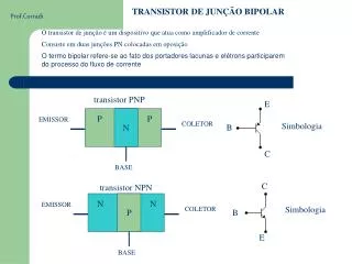
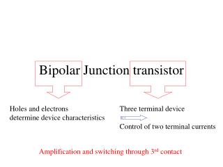
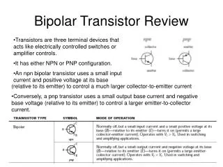
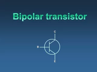
What are the drawbacks of BJT? Injection of holes in Emitter from Base Arpan Deyasi Larger Emitter-Base storage capacitance Electron Effective decrease of electron injection efficiency Device Lowers CE current gain Reduction in speed 5/16/2022 Arpan Deyasi, India 2
Alternative Solutions? I. Increase of Emitter doping Arpan Deyasi Larger Emitter-Base storage capacitance Electron Reduction in speed Device 5/16/2022 Arpan Deyasi, India 3
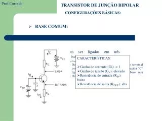
Alternative Solutions? II. Make higher potential barrier for holes in Base region Reduction in minority charge diffusion in Emitter Arpan Deyasi Smaller Emitter-Base storage capacitance Electron Effective increase of electron injection efficiency Device Highers CE current gain Higher operating speed 5/16/2022 Arpan Deyasi, India 4
A. Reduction in Emitter doping Arpan Deyasi Additional benefits Smaller Emitter-Base storage capacitance Electron Higher operating speed Device 5/16/2022 Arpan Deyasi, India 5
Additional benefits B. Higher Base doping Arpan Deyasi Shorter Base Transit time Electron Reduction of depletion region encroachments into Base Reduction in lateral Base resistance Higher current gain – bandwidth product Device Higher power- bandwidth product Higher output conductance Improved high frequency performance Improves noise performance Reduced susceptibility to breakdown 5/16/2022 Arpan Deyasi, India 6
Both electrons and holes will face different barrier height Arpan Deyasi Effects of structural modification Holes are not allowed to go back into emitter Electron Drastic reduction in hole injection from base Device Requirement of higher emitter doping is eliminated Reduction in band narrowing effect 5/16/2022 Arpan Deyasi, India 7
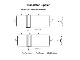
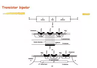
Schematic structure Arpan Deyasi Electron C n-Ge p-GaAs n-GaAs E Device B 5/16/2022 Arpan Deyasi, India 8
Band diagram p-GaAs n-Ge EC2 Arpan Deyasi Ψ2 ΔEC EF Electron Ψ1 EC1 z1 Device z2 EV2 EV1 ΔEV 5/16/2022 Arpan Deyasi, India 9
Arpan Deyasi p-GaAs n-Ge Electron n-GaAs Device 5/16/2022 Arpan Deyasi, India 10
Results parameters Arpan Deyasi Ge GaAs Lattice constant Electron 5.646 Å 5.633 Å Electron affinity 4.0 eV 4.07 eV Bandgap Device 0.8 eV 1.43 eV Conduction band offset ΔEC= (4.07 - 4.0) eV = 0.07 eV Valence band offset ΔEV= (1.43 - 0.8) eV = 0.63 eV 5/16/2022 Arpan Deyasi, India 11
Results Built-in potential Arpan Deyasi = + 1 2 According to charge-neutrality condition Electron Device = z N z N 1 2 D A 5/16/2022 Arpan Deyasi, India 12
Results At junction, electric flux is continuous Arpan Deyasi = = D E E Electron 0 1 1 0 2 2 r r where Device − V − V = E 1 1 = E 2 2 1 z 2 z 1 2 5/16/2022 Arpan Deyasi, India 13
Results Master equation Arpan Deyasi ( − = ( − ) ) V N V N Electron 1 1 1 2 2 2 r D r A Device 5/16/2022 Arpan Deyasi, India 14
Results from calculation Holes and electrons see different barriers Arpan Deyasi Holes are not allowed to reach to Emitter Electron Large reduction in hole injection Device Higher Emitter doping is not required Comparatively lower Emitter doping Lower junction capacitance Higher speed of operation 5/16/2022 Arpan Deyasi, India 15
Advantages of HBT Arpan Deyasi offers low base resistance and low forward transit time due to much higher base doping Electron offers higher cut-off frequency offers very low collector to substrate capacitance due to semi- insulating GaAs substrate Device higher efficiency can be achieved as small base voltage variation can also turn off the HBT device completely offers wideband impedance matching 5/16/2022 Arpan Deyasi, India 16
Disadvantages of HBT Arpan Deyasi Si and SiGe based HBTs offer low breakdown voltage InP HBTs are brittle and expensive substrate Electron Device 5/16/2022 Arpan Deyasi, India 17