Download
1 / 24
300 likes | 1.96k Vues
Counters Photon Counting Chip (PCC) Picture of fuse using PCC Interest The Difference Engine (1872) was a general purpose mechanical calculator solving mathematical problems with up to 31 digit places of accuracy. Through the use of punch-cards, the Analytical Engine could be programmed

E N D
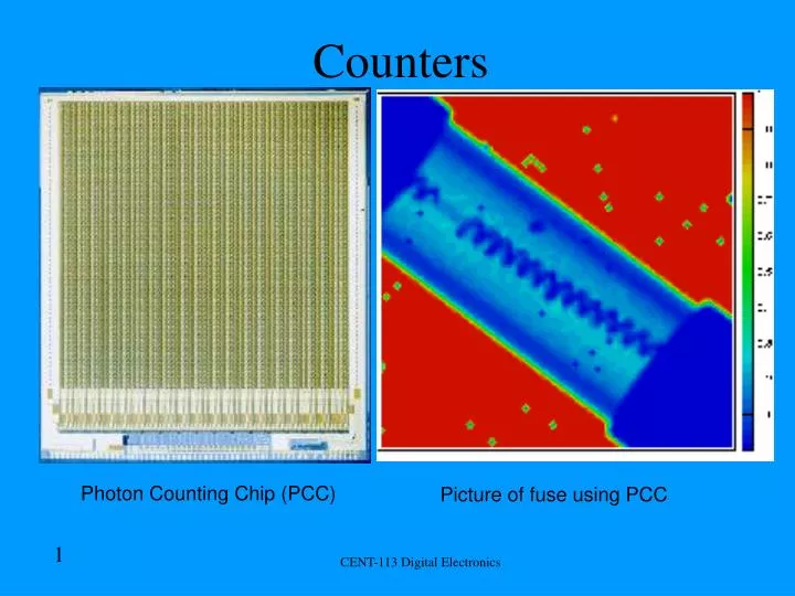
Counters Photon Counting Chip (PCC) Picture of fuse using PCC CENT-113 Digital Electronics
Interest • The Difference Engine (1872) was a general purpose mechanical calculator solving mathematical problems with up to 31 digit places of accuracy. • Through the use of punch-cards, the Analytical Engine could be programmed CENT-113 Digital Electronics
Counters General Information • Purpose: Counting events or periods of time or putting events in sequence. • Other functions: Dividing frequency, addressing, and serving as memory units. • Flip-Flops are wired together forming circuits that count. • Self contained counters in ICs are available in TTL and CMOS. CENT-113 Digital Electronics
Ripple Counters • 4-bit counter: D-C-B-A=8s-4s-2s-1s • 8s: Most Significant Digit/Bit (MSD/B) • 1s: Least Significant Digit/Bit (LSD/B) • BCD count from 0000 to 1111 (Decimal 0-15) • Need a counter with 16 different output states • Mod-16 counter: Modulus of the mod-16 counter undergoes 16 different states to complete the counting cycle. • Mod-16 counter uses 4 J-K flip-flops CENT-113 Digital Electronics
D C B A 1 1 1 1 Q Q Q Q J J J J FF2 FF1 FF4 FF3 CLK CLK CLK CLK 1 1 1 1 K K K K Mod-16 Ripple Counter Clock Pulses BinaryOutput 3 2 4 1 Input Note: The clock triggers only FF1 -Mode 16 means the counter has 16 states. -A ripple counter causes a chain reaction change of FF states. -asynchronous counter means that all FFs do not trigger at The same time. -4 bit counters have 4 binary outputs. 10 6 5 7 9 1 2 8 4 3 CLK FF1 Q FF2 Q FF3 Q FF4 Q CENT-113 Digital Electronics
1 1 1 Q Q Q J J J J FF3 FF2 FF4 FF1 CLK CLK CLK 1 1 1 Mod-10 Ripple Counter • The counting sequence is 0000 to 1001 (0-9). • It has 4 places 8s, 4s, 2s, 1s • NAND gate clears all FF to 0 after the 1001 (9) count. • Also called a decade (meaning 10) counter. Clock Pulses 1 D C B A Q CLK K K K K 1 CLR CLR CLR CLR CENT-113 Digital Electronics
Synchronous Counters • A synchronous counter eliminates the accumulated propagation delay of the ripple counter by tying all clock inputs to a common clock signal. • In a synchronous counter each flip-flop must not be allowed to toggle until all flip-flops that precede it are high (set). • The J-K inputs are tied to an AND gate that ANDs the Q outputs from all previous flip-flops. • Synchronous counters can be used to form any modulus counter by using a NAND gate to reset all the flip-flops. The inputs to the logic gate are from the Q outputs of the flip-flops that form the binary representation of the MOD numbers. • Synchronous counters can be used as down counters by taking the output from the Q rather than the Q of each flip-flop. • Synchronous counters can be used in many of the same design applications as ripple counters. CENT-113 Digital Electronics
1 Q Q J J J FF3 FF2 FF1 CLK CLK 1 K K 3 Bit Mod 8 Synchronous Counter Clock inputs are connected in parallel. Used in high frequency operations. J-K FFs used in toggle or hold modes. Toggle: J=1, K=1 Hold J=0, K=0 C B A Q CLK Clock Pulses K Truth Table CENT-113 Digital Electronics
Questions • Q. What does it mean to be a 3 bit counter? • A. The maximum binary output is 111. • Q. What does it mean to be a Mod-7 counter? • A. There are seven unique counting states in the particular counter. • Q. What is the difference between a synchronous & an asynchronous counter when they both use clock inputs? • A. Most synchronous counters have parallel clocks. CENT-113 Digital Electronics
1 1 1 Q Q Q J J J FF1 FF2 FF3 CLK CLK CLK 1 1 1 K K K Q Q Q 3 Bit Ripple Down Counter Preset Note: A counter that counts higher to lower is called a down counter. It recirculates & goes back to 0111. PS C B A PS PS Clock Pulses Truth Table CENT-113 Digital Electronics
1 1 Q Q J J J FF3 FF1 FF2 CLK CLK 1 1 K K Q Q Q Self-Stopping Counter • Up and down counters can be stopped by using a logic gate. The inputs to J & K at FF1 stops counter and places it in a hold, stopping count at 000. Preset PS C B A Q PS PS Clock Pulses CLK K CENT-113 Digital Electronics
Counters as Frequency Dividers 1 Second Timing Circuit • Counters are used for frequency division. • Uses: Digital clocks & watches, oscilloscopes, and television receivers. • A decade counter can be used as a divide by 10 counter. If a decade counter was used along with a mod-6 counter, the divide by 60 circuit would be designed. Divide by 60 circuit 60 HZ 1 HZ ( 1 pulse per second) CENT-113 Digital Electronics
TTL Counters • 7493 *182 CENT-113 Digital Electronics
Synchronous Up/Down-Counter ICs • The 74192 is a BCD decade up/down synchronous counter. • The 74193 is a 4-bit binary up/down synchronous counter. • These chips have parallel data input leads used to preset the counter. • Two clock inputs are available. 1 UP count & another for a DOWN count. • A terminal count UP and a terminal count DOWN output signal can be used to cascade several ICs together. • Two additional synchronous IC counters are the 74190 and the 74191. • The 74190 is a BCD counter and the 74191 is a 4-bit binary counter. • These chips have a terminal count output and an enable input. With these two connections, cascaded ICs held-off until the proper count. This means that the entire counter can be synchronous. CENT-113 Digital Electronics
CMOS Counters • 74HC393 • 74HC193 CENT-113 Digital Electronics
74HC393 wired as 4-bit Binary Counter • Two 4-bit binary ripple counters, each counter has 4 T-FFs • MR input is an asynchronous master rest pin. • Triggered High to low. • Counts 0000 to 1111. Q3 8s 4s 2s 1s Q2 Clock Pulses Q1 Q0 CLK Counter 74HC393 Reset MR Clear=1 Count=0 CENT-113 Digital Electronics
PL activates the synchronous parallel load with a low just after the highest count of Binary 0110. +5V disables the CPD & ground disables MR. PL 74HC193 wired as Mod-6 Counter • 74HC193 is a presettable synchronous 4-bit binary up/down counter IC • Clock edge triggered low to high. • Modes of operation: reset, parallel load, count up, count down Q3 8s 4s 2s 1s Q2 Q1 A Q0 Counter 74HC193 B C D +5V Clock Pulses CPD Count Down CPU Count Up MR CENT-113 Digital Electronics
Counting System using Optical Encoder +5V +5V +5V +5V 1 Optoisolator 4N25 4 Common Anode LED 1 +5V Decade Counter 74193 Decoder/Driver 7447 Count Up 7414 2 2N3904NPN 3 CLR GND GND CENT-113 Digital Electronics
74HC85 Comparator IC • The 74HC/HCT85 are high-speed CMOS devices and are pin compatible with low power Schottky TTL (LSTTL). • The 74HC/HCT85 are 4-bit magnitude comparators that can be expanded to almost any length. They perform comparison of two 4-bit binary, BCD or other monotonic codes and present the three possible magnitude results at the outputs (QA>B, QA=B and QA<B). The 4-bit inputs are weighted (A0 to A3 and B0 to B3), where A3 and B3 are the most significant bits. CENT-113 Digital Electronics
L= Low logic level H= High logic level X= Don’t care 74HC85 Comparator IC Continued Pin Diagram Truth Diagram Data Inputs A3 B2 A2 A1 B1 A0 B0 Vcc 16 15 14 13 12 11 10 9 1 2 3 4 5 6 7 8 A>B A=B A<B A>B A=B A<B B3 GND Data Input Cascade Inputs Outputs -Two 4-bit comparators can be cascaded to compare 8 bit numbers or words. -Cascading means joined to another. CENT-113 Digital Electronics
Sequential Logic Troubleshooting Tools • Commercial Logic Probe (TTL/CMOS SS) & (MEM/PULSE SS) In MEM any signal (0 or 1) can pulse (as short as 50ns) will activate the pulse LED. • Digital Logic Pulser: Lets you generate a signal. CENT-113 Digital Electronics
Sequential Logic Troubleshooting Tools • Logic monitors with IC clips check chips in circuits with each pin lit by LED. • Portable IC tester tests chips out of circuit. • Handheld Oscilloscope. CENT-113 Digital Electronics
Troubleshooting a Counter • Use best tool. • Use 5 senses to troubleshoot. • Check powers supply and common. • Use logic monitor to observe counting operation. • Check reset. • Check bent pins CENT-113 Digital Electronics
Conclusions • A. What is the difference between a FF and a counting circuit? • Q. FFs are the building blocks for counting circuits. CENT-113 Digital Electronics