Download
1 / 87
1.11k likes | 2.16k Vues
Types of Semiconductors. Semiconductors can be classified as: Intrinsic Semiconductor. Extrinsic Semiconductor. Extrinsic Semiconductors are further classified as: a. n-type Semiconductors. b. p-type Semiconductors. Intrinsic Semiconductor.

E N D
Types of Semiconductors • Semiconductors can be classified as: • Intrinsic Semiconductor. • Extrinsic Semiconductor. • Extrinsic Semiconductors are further classified as: • a. n-type Semiconductors. • b. p-type Semiconductors. AEI105.120
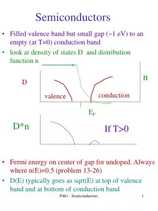
Intrinsic Semiconductor • Semiconductor in pure form is known as Intrinsic Semiconductor. • Ex. Pure Germanium, Pure Silicon. • At room temp. no of electrons equal to no. of holes. Si Si Si FREE ELECTRON Si Si Si HOLE Si Si Si Fig 1. AEI105.120
Intrinsic semiconductor energy band diagram Fermi level lies in the middle Conduction Band FERMI LEVEL Energy in ev Valence Band Fig 2. AEI105.120
Extrinsic Semiconductor • When we add an impurity to pure semiconductor to increase the charge carriers then it becomes an Extrinsic Semiconductor. • In extrinsic semiconductor without breaking the covalent bonds we can increase the charge carriers. AEI105.120
Intrinsic Semiconductor It is in pure form. 2. Holes and electrons are equal. Extrinsic Semiconductor It is formed by adding trivalent or pentavalent impurity to a pure semiconductor. No. of holes are more in p-type and no. of electrons are more in n-type. Comparison of semiconductors AEI105.120
(Cont.,) • 3. Fermi level lies near • valence band in p-type and • near conduction band in n-type. • 4. Ratio of majority and • minority carriers are equal. 3. Fermi level lies in between valence and conduction Bands. 4. Ratio of majority and minority carriers is unity. AEI105.120
N-type Pentavalent impurities are added. Majority carriers are electrons. Minority carriers are holes. Fermi level is near the conduction band. P-type Trivalent impurities are added. Majority carriers are holes. Minority carriers are electrons. Fermi level is near the valence band. Comparison between n-type and p-typesemiconductors AEI105.120
N-type Semiconductor • When we add a pentavalent impurity to pure semiconductor we get n-type semiconductor. As Pure si N-type Si Fig 1. AEI105.121 to 122
N-type Semiconductor • Arsenic atom has 5 valence electrons. • Fifth electron is superfluous, becomes free electron and enters into conduction band. • Therefore pentavalent impurity donates one electron and becomes positive donor ion. Pentavalent impurity known as donor. AEI105.121 to 122
P-type Semiconductor • When we add a Trivalent impurity to pure semiconductor we get p-type semiconductor. Ga Pure si P-type Si Fig 2. AEI105.121 to 122
P-type Semiconductor • Gallium atom has 3 valence electrons. • It makes covalent bonds with adjacent three electrons of silicon atom. • There is a deficiency of one covalent bond and creates a hole. • Therefore trivalent impurity accepts one electron and becomes negative acceptor ion. Trivalent impurity known as acceptor. AEI105.121 to 122
Carriers in P-type Semiconductor • In addition to this, some of the covalent bonds break due temperature and electron hole pairs generates. • Holes are majority carriers and electrons are minority carriers. AEI105.121 to 122
P and N type Semiconductors P Acceptor ion Donor ion N + - - - + + + - + - + + + - - - + - + + - - Minority hole Minority electron Majority holes Majority electrons Fig 3. AEI105.121 to 122
Intrinsic Semiconductor It is in pure form. Holes and electrons are equal. Fermi level lies in between valence and conduction Bands. Extrinsic Semiconductor It formed by adding trivalent or pentavalent impurity to a pure semiconductor. No. of holes are more in p-type and no. of electrons are more in n-type. Fermi level lies near valence band in p-type and near conduction band in n-type. Comparison of semiconductors AEI105.121 to 122
Conduction in Semiconductors Conduction is carried out by means of 1. Drift Process. 2. Diffusion Process. AEI105.121 to 122
Drift process A B CB VB V Fig 4. • Electrons move from external circuit and in conduction band of a semiconductor. • Holes move in valence band of a semiconductor. AEI105.121 to 122
Diffusion process • Moving of electrons from higher concentration gradient to lower concentration gradient is known as diffusion process. X=a Fig 5. AEI105.121 to 122
P and N type Semiconductors P Acceptor ion Donor ion N + - - - + + + - + - + + + - - - + - + + - - Minority hole Minority electron Majority holes Majority electrons Fig 1. AEI105.123
Formation of pn diode Depletion Region P N + - - - + + + - + - + + + - - - + - + + - - Fig 2. Potential barrier Vb AEI105.123
Formation of pn diode • A P-N junction is formed , if donor impurities are introduced into one side ,and acceptor impurities Into other side of a single crystal of semiconductor • Initially there are P type carriers to the left side of the junction and N type carriers to the right side as shown in figure 1 AEI105.123
On formation of pn junction electrons from n-layer and holes from p-layer diffuse towards the junction and recombination takes place at the junction. • And leaves an immobile positive donor ions at n-side and negative acceptor ions at p-side. AEI105.123
Formation of pn diode • A potential barrier develops at the junction whose voltage is 0.3V for germanium and 0.7V for silicon. • Then further diffusion stops and results a depletion region at the junction. AEI105.123
Depletion region • Since the region of the junction is depleted of mobile charges it is called the depletion region or the space charge region or the transition region. • The thickness of this region is of the order of 0.5 micrometers AEI105.123
Circuit symbol of pn diode • Arrow head indicates the direction of conventional current flow. A K Fig 3. AEI105.123
P-N Junction Diode- Forward Biasing Fig. 1 P-N junction with FB AEI105.124
Working of P-N Junction under FB P N V Potential barrier Fig. 2 Working of P-N junction AEI105.124
Forward Bias • An ext. Battery applied with +ve on p-side, −ve on n- side. • The holes on p-side repelled from the +ve bias, the electrons on n- side repelled from the −ve bias . • The majority charge carriers driven towards the junction. • This results in reduction of depletion layer width and barrier potential. • As the applied bias steadily increased from zero onwards the majority charge carriers attempts to cross junction. AEI105.124
Holes from p-side flow across to the −ve terminal on the n-side, and electrons from n-side flow across to the +ve terminal on the p-side. • As the ext. bias exceeds the Junction barrier potential (0.3 V for Germanium, 0.7 V for Silicon ) the current starts to increase at an exponential rate. • Now, a little increase in forward bias will cause steep rise in majority current. • The device simply behaves as a low resistance path. AEI105.124
Features: • Behaves as a low resistor. • The current is mainly due to the flow of majority carriers across the junction. • Potential barrier, and the depletion layer is reduced AEI105.124
Current components Fig. 3 Current components AEI105.124
P-N Junction Diode- Reverse Biasing Fig.1 P-N Junction Diode with Reverse bias (RB) AEI105.125
P-N Junction working under reverse bias P N Fig.2 P-N Junction Diode working under RB V Potential barrier AEI105.125
P-N Junction Diode- Reverse Bias • External bias voltage applied with +ve on n-side, −ve on p- side. • This RB bias aids the internal field. • The majority carriers i.e. holes on p-side, the electrons on n- side attracted by the negative and positive terminal of the supply respectively. • This widens the depletion layer width and strengthens the barrier potential. AEI105.125
Few hole-electron pairs are created due to thermal agitation (minority carriers). • As a result small current flows across the junction called as reverse saturation current I0 (uA for Germanium, nA for Silicon). • Behaves as a high impedance element. AEI105.125
Further rise in reverse bias causes the collapse of junction barrier called breakdown of the diode. • This causes sudden increase in flow of carriers across the junction and causes abrupt increase in current. AEI105.125
P-N JUNCTION Fig 1. AEI105.126
JUNCTION PROPERTIES • The junction contains immobile ions i.e. this region is depleted of mobile charges. • This region is called the depletion region, the space charge region, or transition region. • It is in the order of 1 micron width. • The cut-in voltage is 0.3v for Ge, 0.6v for Si. AEI105.126
(Contd..) 5. The reverse saturation current doubles for every 10 degree Celsius rise in temperature. 6. Forward resistance is in the order ohms, the reverse resistance is in the order mega ohms. 7. The Transition region increases with reverse bias this region also considered as a variable capacitor and known as Transition capacitance AEI105.126
V-I Characteristics of P-N Junction Diode Fig 2. AEI105.126
(Contd…) IF(mA) Forward bias Breakdown voltage VR(V) VF(V) Cutin voltage Reverse Bias Fig 3. IR(uA) AEI105.126
Diode Current The expression for Diode current is Where Io=Reverse Saturation current. V=Applied Voltage. Vt=Volt equivalent temperature=T(K)/11600. n=1 for germanium and 2 for silicon. AEI105.126
Resistance calculation IF(mA) Forward bias Breakdown voltage ΔV If Vr ΔI VR(V) VF(V) Vf Ir Cutin voltage Reverse Bias Fig 4. IR(uA) AEI105.126
Resistance calculation Forward Resistance 1. Dynamic resistance (rf)= ΔV/ ΔI ..ohms. Where ΔV, ΔI are incremental voltage and current values on Forward characteristics. 2. Static resistance (Rf)= Vf /If …ohms. Where Vf, If are voltage and current values on Forward characteristics. AEI105.126
(Contd..) Reverse Resistance: Static resistance = Vr /Ir …ohms Where Vr, Ir are voltage and current values on Reverse characteristics. AEI105.126
Diode-Variants • Rectifier diodes: These diodes are used for AC to DC conversion Over voltage protection. • Signal diodes : Detection of signals in AM/FM Receivers. • Zener diode: Voltage Regulation purpose. • Varactor diode for variable capacitance Electronic tuning commonly used in TV receivers. AEI105.127
(contd…) • Light Emitting Diodes (LED) : Display Light source in Fiber optic comm. • Photo diodes : Light detectors in Fiber optic comm. • Tunnel diode: Negative resistance for Microwave oscillations • Gunn diode :Microwave Oscillator. • Shottkey diode: High speed Logic circuits AEI105.127
Semiconductor diodes Fig. 1 Diode variants Visual - 1 AEI105.127
Diode numbering First Standard (EIA/JEDEC): In this approach the semiconductor devices are identified with the no of junctions. 1N series : single junction devices such as P-N junction Diode. e.g.: 1N4001,1N3020. 2N series : Two junction devices such as Transistors. e.g.: 2N2102,1N3904. EIA= Electronic Industries association JDEC=Joint Electron Engineering Council. AEI105.127
(contd…) Second Standard In this method devices given with alpha-numeric codes. And each alphabet has a specific information which tells about application, material of fabrication. First Letter: material A=Germanium. B=Silicon. C=Gallium arsenide. R=compound material (e.g. Cadmium sulphide). AEI105.127