Download
1 / 33
340 likes | 930 Vues
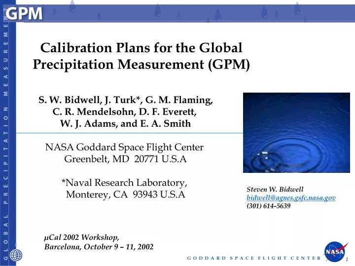
Calibration Plans for the Global Precipitation Measurement (GPM) S. W. Bidwell, J. Turk*, G. M. Flaming, C. R. Mendelsohn, D. F. Everett, W. J. Adams, and E. A. Smith NASA Goddard Space Flight Center Greenbelt, MD 20771 U.S.A *Naval Research Laboratory, Monterey, CA 93943 U.S.A

E N D
Calibration Plans for the Global Precipitation Measurement (GPM) S. W. Bidwell, J. Turk*, G. M. Flaming, C. R. Mendelsohn, D. F. Everett, W. J. Adams, and E. A. Smith NASA Goddard Space Flight Center Greenbelt, MD 20771 U.S.A *Naval Research Laboratory, Monterey, CA 93943 U.S.A Steven W. Bidwell bidwell@agnes.gsfc.nasa.gov (301) 614-5639 µCal 2002 Workshop, Barcelona, October 9 – 11, 2002
GPM Calibration Plans Outline Outline • GPM Overview • GMI Instrument • GPM Calibration • IV. Conclusions
I. GPM Overview GPM Overview
OBJECTIVES • Understand horizontal & vertical structure of rainfall, its macro- & micro-physical nature, & its associated latent heating • Transfer Standard for constellation radiometers • OBJECTIVES • Provide sufficient global sampling to significantly reduce uncertainties in short-term rainfall accumulations • Extend scientific and societal applications GPM Concept Constellation Core • Core Satellite • TRMM-like spacecraft (NASA) • H2-A rocket launch (NASDA) • Non-sun-synchronous orbit • ~ 65° inclination • ~400 km altitude • Dual frequency radar (NASDA) • Ku-Ka Bands (14-35 GHz) • ~ 5 km horizontal resolution • ~250 m vertical resolution • Multifrequency radiometer (NASA) • 10, 19, 23, 36, 89, (150/183 ?) GHz V&H • Constellation Satellites • Pre-existing operational-experimental & dedicated satellites with microwave / millimeter-wave radiometers • Revisit time • 3-hour goal at ~90% of time • Sun-synch & non-sun- synch orbits • 600-900 km altitudes • Precipitation Validation Sites for Error Characterization • Select/globally distributed ground validation “Supersites” (research quality radar, up looking radiometer-radar-profiler system, raingage-disdrometer network, & T-q soundings) • Dense & frequently reporting regional raingage networks • Precipitation Processing System • Produces global precipitation products • Products defined by GPM partners
GPM Core Satellite Instruments 35.55 GHz radar (phased array) GMI Microwave Radiometer 13.6 GHz radar (Similar to TRMM PR phased array) + Possible “Instrument of Opportunity”
Core Satellite Observations Flight Direction Surface Track Speed = 7.2 km/s Altitude = 400 km DPR Dual-frequency Precipitation Radar Ku and Ka Bands GMI Microwave Radiometer PR-U Swath Width= 245 km PR-A Swath Width = 100 km GMI Swath Width = 890 km 5 km
GPM Sampling Goal Percentage of 3-Hour Intervals Sampled in 7-Day Period (Simulation) EOS Era 2002-2007 GPM Era 2007-2010 GPM Core, GPM Constellation, DMSP F18, DMSP F19, GCOM-B1, Megha-Tropiques, Euro-GPM, and Additional Partner TRMM, DMSP F13, F14, F15, AQUA, and ADEOS-II Constant Area Pixels
II. GMI Instrument GMI Instrument
GMI Parameters Highlights represent some changes from TRMM (TMI Requirements in parentheses)
GMI Performance Enhancements GMI Enhancements in Order of Preference: • 1) Improved surface spatial resolution on low frequency channels (10.65 GHz, 18.7 GHz, 23.8 GHz) • Implies: an antenna diameter increase to 1.2 meters • Improved capabilities for the measurement of light rain and snow • Specifically: 150 GHz or 166 GHz (V and H) • 183 GHz ±1, ±3, ±6, ±9 GHz (V or H) • Complete surface scene sampling on all channels • Implies: multiple 89 GHz feedhorns to ensure swath contiguity
High Frequency Channels Snowfall Over Ocean Courtesy of: Prof. Guosheng Liu/FSU Suggested primary channels for snow detection are 163 GHz at V-pol & H-pol. Dual polarization allows use of PCT which is more sensitive to snowfall than any single polarization. If only one polarization is possible, use V-pol instead of H-pol, because dynamic range is much greater at V-pol (i.e., background is much warmer).
High Frequency Channels Snowfall Over Land Courtesy of: Prof. Guosheng Liu/FSU Suggested primary channels for snow detection are 183±3 & 183±9, both at V-pol. First channel is for low water vapor densities while second is for high water vapor densities.
Radiometer Altitude / Resolution Comparisons SSMI (0.61 m) CMIS (2.2 m) AMSR-E (1.6 m) GMI Const. (1.0 m) Orbital Altitude (km) GMI Core (1.0 m) TMI (0.61 m) 30 km 17 km 10.65 GHz Resolution (km) 18.7 GHz / 19.35 GHz
GMI Down-Track (Cross-Scan) Sampling • GMI will have increased resolution than TRMM at 10, 18, and 21 GHz • GMI will have similar resolution to TRMM at 36 and 89 GHz • Contiguity is required at 36 GHz • Rotational rates greater than 40 rpm viewed with caution
III. GPM Calibration GPM Calibration
GPM Transfer Standard • What is meant by a Transfer Standard? • Two distinct things: • GMI as the Radiometric Calibration Standard • Core Satellite Retrievals as the Precipitation Standard • ___________________________________ • (1) GMI as the Radiometric Calibration Standard: • For GPM purposes, the GMI aboard the Core satellite will act as a calibration reference for the conically scanning member radiometers of GPM, e.g.: • SSMI, AMSR, CMIS, MADRAS, GPM Const. GMI, • E-GPM, etc. • As a routine GPM procedure, prior to processing and ‘merging’ of data, calibrations of other sensors will be adjusted for consistency with the GMI.
GMI Radiometric Calibration Standard • Why the Core Satellite GMI as the Calibration Reference? • The Core GMI is NASA-managed throughout mission life • (i.e. its calibration will be well-understood by GPM) • The Core GMI will have an excellent on-board calibration system • The Core GMI will have the highest spatial resolution amongst • sensors • One instrument needs to be designated as the standard
Precipitation Standard (2) Core Satellite Retrievals as the Precipitation Standard: What is the Precipitation Transfer Standard? The Core Satellite combined radar / radiometer retrievals will create a data base ‘standard’ of observed brightness temperatures, precipitation systems, and precipitation structures Retrievals using GPM Constellation Radiometers will access the data base standard to choose optimal precipitation parameters consistent with its brightness temperature observations (similar to Goddard Profiling Algorithm GPROF currently in use) Why the Core Satellite as the Precipitation Transfer Standard? The Core Satellite is a unique platform with the combined Dual-frequency Precipitation Radar (DPR) and GMI Radiometer
External Calibration • External Calibration Methods • (1) Radiometer Calibrations with an Absolute Reference at the Ground Validation (GV) Sites: • Tropical Oceanic Site • Tropical Continental Site (uniform vegetation) • Under clear sky conditions, with GV measurement of: • water vapor and temperature profiles • surface state conditions • Inter-Sensor Comparison Events: • Orbital intersections (Core with Constellation Members) with swath overlap within specified time delay and spatial separation
GPM Ground Validation Potential Supersites and Regional Raingauge Networks North Europe BALTEX Canada England EC NASA Land South Korea ARM/UOK Japan NASA KSC Taiwan NASA Ocean Brazil Regional Raingauge Network Supersite & Regional Raingauge Network Supersite
GPM Ground Validation Supersite Template Data Analysis Facility Multi-Parameter Radar { Matched Dual Freq. Radar & Multi-Channel Radiometer S-/X- Band Radars / Profilers Cloud Radar Profiler Meteorological Tower & Sounding System Site Scientist (3) DELIVERY Technician (3) 150 km • GV Products • (1) Error Biases & Bias Uncertainties • (2) Error Structures / Error Covariances • GV Product Customers • (1) Data Assimilation Specialists • (2) Climate Diagnosticians • (3) Algorithm Specialists Low Resolution Domain 100-Gauge Site, Centered on Multi-Parameter Radar 150 km 5 km Triple Gauge Site (3 Economy Scientific Gauges) • High Resolution Domain • 50-Gauge Site, Center-Displaced with • Matched Radar / Radiometer [ 14, 35 / 10, 19, 22, 37, 85 GHz ] • S-/X-band Doppler Radar Profilers • Cloud Radar Profiler Single Disdrometer/ Triple Gauge Site (1 High Quality-Large Aperture/ 2 Economy Scientific Gauges)
Azimuth Viewing Differences Example: An Aqua (AMSR-E swath in red) overpass occurs, then a GPM core (GMI swath in blue, simulated by the TMI instrument) follows Δt minutes later. The Δt offset is complicated by the fact that although the satellite zenith angles are designed to be the same, their azimuth angles are different. AMSR on-Earth beam projection GMI on-Earth beam projection
Inter-Sensor Comparisons / No Rain Narrower beamwidth 85 GHz channels (red) sense primarily along-path water vapor and cloud, and some of the surface (more so for drier atmospheres) Wider beamwidth, lower frequency channels (green) sense along-path cloud and azimuthal variations of surface wind speed and direction (+/-3 K) Over land, variations arise from variable soil conditions (not drawn to any scale)
Inter-Sensor Comparisons / No Rain Baseline No-Rain Conditions, Coincident TMI-SSMI land water T=3 months Δt=1 minute Δd=10 km TMI=no-rain, 3x3 ave
Inter–Sensor Comparisons / No Rain Baseline No-Rain Conditions, Coincident TMI-SSMI (binned) land water T=3 months Δt=1 minute Δd=10 km TMI=no-rain, 3x3 ave, then binned to 1-degree
Inter-Sensor Comparisons / Raining Conditions Narrower beamwidth 85 GHz channels (red) sense higher in the cloud, but horizontal asymmetries give rise to large TB variations depending upon azimuth view Wider beamwidth, lower frequency channels (green) sense lower in the cloud where horizontal asymmetries are smaller The 3-D effects should average-out with many events and with spatial averaging (not drawn to any scale)
Inter-Sensor Comparisons / Raining Conditions Raining Conditions, Coincident TMI-SSMI land water 3-D effects Δt=1 minute Δd=10 km TMI rainflag=rain, 3x3 average Nocean=13433 Nland=1320
Inter-Sensor Comparisons / Raining Conditions Rainy Conditions, Coincident TMI-SSMI TMI-SSMI Difference vs. TMI 2A12 Rain Rate Δt=1 minute Δd=10 km TMI rainflag=rain, 3x3 average Nocean=13433 Nland=1320
Inter-Sensor Comparisons / Raining Conditions Rainy Conditions, Coincident TMI-SSMI TMI-SSMI Difference vs. Relative Azimuth Δt=1 minute Δd=10 km TMI rainflag=rain, 3x3 ave N=5336
IV. Conclusions Conclusions • NASA will procure two radiometers, GPM Microwave Imagers (GMI), for the GPM. • Core GMI Calibration will be used as a Reference Standard for the Constellation Member Radiometers. • GPM plans External Calibration Techniques for Calibrating the Core GMI: • (1) Ground Validation System and • (2) Inter-Sensor Comparisons from Swath Intersection Events.


![Downes v. Bidwell (1901) [Insular Cases]](https://cdn1.slideserve.com/2052337/slide1-dt.jpg)