Download
1 / 23
230 likes | 500 Vues
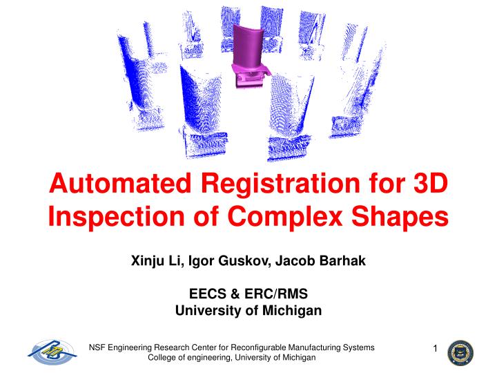
Automated Registration for 3D Inspection of Complex Shapes. Xinju Li, Igor Guskov, Jacob Barhak EECS & ERC/RMS University of Michigan. Challenge. Develop methodology for inspection of surfaces with complex geometry . Challenge in Inspection: Part Alignment.

E N D
Automated Registration for 3D Inspection of Complex Shapes Xinju Li, Igor Guskov, Jacob Barhak EECS & ERC/RMS University of Michigan NSF Engineering Research Center for Reconfigurable Manufacturing Systems College of engineering, University of Michigan
Challenge • Develop methodologyfor inspection of surfaces withcomplex geometry. NSF Engineering Research Center for Reconfigurable Manufacturing Systems College of engineering, University of Michigan
Challenge in Inspection: Part Alignment • Coordinate systemregistrationisrequiredsince measured data and the CAD model arenot in the same coordinate system NSF Engineering Research Center for Reconfigurable Manufacturing Systems College of engineering, University of Michigan
Common Practice PhysicalPart Alignment: Fixture dependant A calibration-like process prior to the physical inspection The part coordinate system is established by measuring locators Computing power allows ComputationalPart Alignment: Fixtureless The Alignment is preformed after measurement acquisition The nominal shape establishes the part coordinate system Part Alignment - From Common Practice to Computing Power NSF Engineering Research Center for Reconfigurable Manufacturing Systems College of engineering, University of Michigan
Approach Advantages • No fixturerequired for inspection • Free-orientationinspectionpossible • Save design time • Save in manufacturing resources • Save time allotted for mounting the part in the fixture • Increased part exposure during inspection • A simplified inspection plan • Does not require prior knowledge of the inspected part • Save time in designing the inspection plan • Decoupleacquisition and alignmentstages • Less physicalinteraction NSF Engineering Research Center for Reconfigurable Manufacturing Systems College of engineering, University of Michigan
More Advantages • Improvedinformation flowbetween processes in modern environment • Noneed inDatumdefinition for inspection • TheCAD modelis the nominal shape • Rapid prototypedparts can be easily inspected • Inspectionmachine capabilities increase • Part size is not limited toinspection volume • Systematic errorscan becompensatedfor • Suitsvarious machinesemploying non-contact probes NSF Engineering Research Center for Reconfigurable Manufacturing Systems College of engineering, University of Michigan
Inspection and Alignment Methodology 3D CAD model ComputationalPart Alignment Inspection Initial Pose Estimation (Approximate solution) Acquired 3D Data Solution Refinement Iterate Closest Point (ICP) algorithm Shape Deviation (Manufacturing error) NSF Engineering Research Center for Reconfigurable Manufacturing Systems College of engineering, University of Michigan
Inspection Approach is Similar to Reverse Engineering Measurement from a single direction Multi-scan from 12 directions NSF Engineering Research Center for Reconfigurable Manufacturing Systems College of engineering, University of Michigan
Alignment by Registration for Reverse Engineering and for Inspection Inspection: Registration between a point cloud and the CAD model Reverse Engineering: Registration between clouds of points acquired from different vantages NSF Engineering Research Center for Reconfigurable Manufacturing Systems College of engineering, University of Michigan
Inspection and Alignment Methodology 3D CAD model ComputationalPart Alignment Inspection Initial Pose Estimation (Approximate solution) Acquired 3D Data Solution Refinement Iterate Closest Point (ICP) algorithm Shape Deviation (Manufacturing error) NSF Engineering Research Center for Reconfigurable Manufacturing Systems College of engineering, University of Michigan
Overview • Scans and models are point clouds with normals • A scan is considered part of its model • Feature points are detected and matched Before matching After initial matching Method by Xinju Li and Igor Guskov NSF Engineering Research Center for Reconfigurable Manufacturing Systems College of engineering, University of Michigan
Point Selection • Multi-scale feature points are used to minimize the matching effort using: • Xinju Li, Igor Guskov, “Multi-scale Features for Approximate Alignment of Point-based Surfaces” (SGP05) http://graphics.eecs.umich.edu/dgp/mrfet-electronic.pdf • Build multi-scale representation of the surface by a smoothing procedure • Compute the normal difference between neighbor levels • Feature points are local maximal or minimal of normal difference Scan and model : feature points are marked with yellow circles NSF Engineering Research Center for Reconfigurable Manufacturing Systems College of engineering, University of Michigan
- - - + + + Point Selection Multi-scale representation Normal difference Feature points are local maxima or minima on the normal difference of the surface Method by: Xinju Li and Igor Guskov NSF Engineering Research Center for Reconfigurable Manufacturing Systems College of engineering, University of Michigan
Matching and Transformation • Calculate transform for all feature pairs • Select best transform according to distance criteria Normal Principal Curvature Direction Method by: Xinju Li and Igor Guskov NSF Engineering Research Center for Reconfigurable Manufacturing Systems College of engineering, University of Michigan
Inspection and Alignment Methodology 3D CAD model ComputationalPart Alignment Inspection Initial Pose Estimation (Approximate solution) Acquired 3D Data Solution Refinement Iterate Closest Point (ICP) algorithm Shape Deviation (Manufacturing error) NSF Engineering Research Center for Reconfigurable Manufacturing Systems College of engineering, University of Michigan
Solution Refinement: ICP Algorithm Given a point cloud {pi} and a CAD model of the part For every cloud point pi find the closest pointqi on the model Find the transformationT to minimize distance sum || pi - T qi||2 Iterate the process until it converges Output the Deviation Graphics by: Liang Zhu NSF Engineering Research Center for Reconfigurable Manufacturing Systems College of engineering, University of Michigan
Output: Shape Verification Model: 69668 Vertices; 139,336 Faces Scan: 26,757 sampled points in 12 scans NSF Engineering Research Center for Reconfigurable Manufacturing Systems College of engineering, University of Michigan
Output: Shape Verification Model: 882,954 Vertices; 1,765,388 Faces Simplified: 50,054 Vertices, 100,000 Faces Scan: 87,903 sampled points in 12 scans NSF Engineering Research Center for Reconfigurable Manufacturing Systems College of engineering, University of Michigan
Output: Shape Verification Model: 530,168 Vertices; 1,060,346 Faces Simplified: 49996 Vertices; 100,000 Faces Scan: 31,677 sampled points in 12 scans NSF Engineering Research Center for Reconfigurable Manufacturing Systems College of engineering, University of Michigan
Additional Information • J. Barhak, “Utilizing Computing Power to Simplify the Inspection Process of Complex Shapes”. The 2004 Israel-Italy Bi-National Conference on Measurements and Uncertainty Evaluation in Coordinate Measuring Machine (CMM) and Scanners and their Implication on Design and Reverse Engineering. Haifa, Israel, November 29-30, 2004. • L. Zhu, J. Barhak, V. Srivatsan, R. Katz, “Error Analysis and Simulation for Four-Axis Optical Inspection System”, Digital Enterprise Technology, September 13-15, 2004, Seattle, Washington, USA. • L. Zhu, J. Barhak, V. Srivatsan, R. Katz, “Efficient Registration for Precision Inspection of Free-Form Surfaces”, Accepted by the International Journal of Advanced Manufacturing Technology. NSF Engineering Research Center for Reconfigurable Manufacturing Systems College of engineering, University of Michigan
Conclusions • Multi-view inspection offers many advantages, especially in conjunction with contemporary non-contact devices. • Computing power is an essential component in dealing with multi-view inspection. NSF Engineering Research Center for Reconfigurable Manufacturing Systems College of engineering, University of Michigan
Acknowledgements • Research supported by the NSF Engineering Research Center for Reconfigurable Manufacturing Systems(ERC/RMS) under the grant EEC-9529125 • This work was also supported in part by NSF CAREER award (CCR-0133554) • Prof. Yoram Koren for supporting these projects • Geoffrey Blake andSher Jun Tan for programming • Dr.Liang Zhu and Vijay Srivatsan for their help in developing the 3D inspection approach • Special thanks to Steve Erskine for his aid in system construction • Neil Craft from Williams International for his consultation • Szymon Rusinkiewicz for his consultation at early stages of the work • Additional thanks to the UM3D Lab director Dr.-Ing. Klaus-Peter Beier and Brett Lyons for manufacturing the models • Cyberware.com web site for the hip bone model • Large Geometric Models Archive at Georgia Institute of Technology for the Turbine blade model • The Arrigo dataset are courtesy of the Visual Computing Lab of CNR-IS TI, Pisa, Italy NSF Engineering Research Center for Reconfigurable Manufacturing Systems College of engineering, University of Michigan
Thank you for your attention!! Your feedback and questions are welcome NSF Engineering Research Center for Reconfigurable Manufacturing Systems College of engineering, University of Michigan