Download
1 / 31
2.1k likes | 5.99k Vues
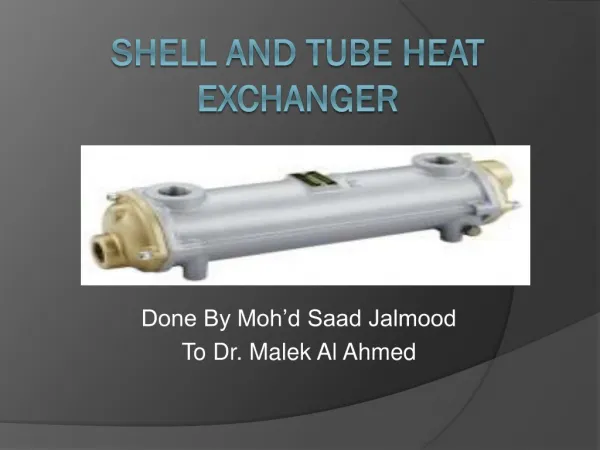
Shell-and-Tube Heat Exchangers. Introduction to Heat Exchanger. A heat exchanger can be defined as any device that transfers heat from one fluid to another or from or to a fluid and the environment. Whereas in direct contact heat exchangers, there is no intervening surface between fluids

E N D
Introduction to Heat Exchanger • A heat exchanger can be defined as any device that transfers heat from one fluid to another or from or to a fluid and the environment. • Whereas in direct contact heat exchangers, there is no intervening surface between fluids • In indirect contact heat exchangers, the customary definition pertains to a device that is employed in the transfer of heat between two fluids or between a surface and a fluid
Why shell-and-tube? CEC survey: S&T accounted for 85% of new exchangers supplied to oil-refining, chemical, petrochemical and power companies in leading European countries. Why? • Can be designed for almost any duty with a very wide range of temperatures and pressures • Can be built in many materials • Many suppliers • Repair can be by non-specialists • Design methods and mechanical codes have been established from many years of experience
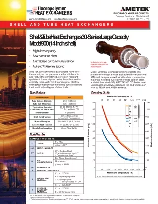
Scope of shell-and-tube • Maximum pressure • Shell 300 bar (4500 psia) • Tube 1400 bar (20000 psia) • Temperature range • Maximum 600oC (1100oF) or even 650oC • Minimum -100oC (-150oF) • Fluids • Subject to materials • Available in a wide range of materials • Size per unit 100 - 10000 ft2 (10 - 1000 m2) Can be extended with special designs/materials
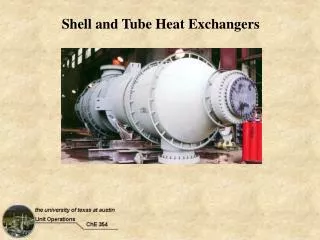
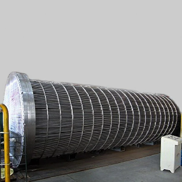
Construction • Bundle of tubes in large cylindrical shell • Baffles used both to support the tubes and to direct into multiple cross flow • Headers • Types Shell Tubes Baffle
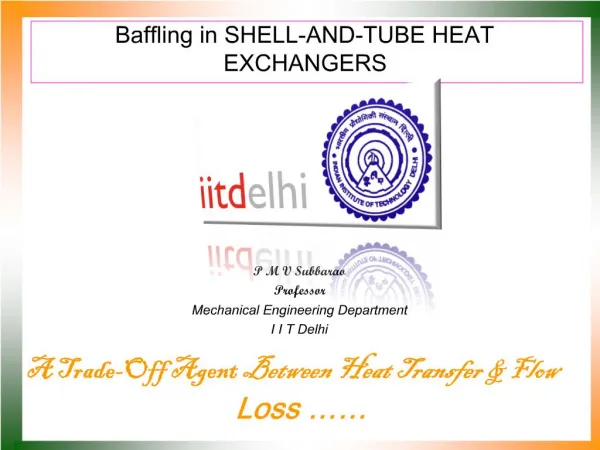
Baffle Type and Geometry • Baffles support the tubes for structural rigidity, thus prevent tube vibration and sagging • They also divert the flow across the tube bundle to obtain a higher heat transfer coefficient • Baffles can be transverse or longitudinal • Transverse baffles are plate type or rod type • Plate baffles • single and double segmental most common • baffle spacing is critical (optimum between 0.4 and 0.6 of the shell diameter) • triple and no-tubes-in-window segmental baffles for low pressure drop applications
Avoiding vibration (cont.) Inlet support baffles Double-segmental baffles Intermediate baffles Windows with no tubes Tubes No tubes in the window - with intermediate support baffles
RODbaffles Tend to be about 10% more expensive for the same shell diameter
TEMA terminology • Letters given for the front end, shell and rear end types • Exchanger given three letter designation Rear end head type Front end stationary head type Shell
Front head type • A-type is standard for dirty tube side • B-type for clean tube side duties. Use if possible since cheap and simple. B A Channel and removable cover Bonnet (integral cover)
More front-end head types • C-type with removable shell for hazardous tube-side fluids, heavy bundles or services that need frequent shell-side cleaning • N-type for fixed for hazardous fluids on shell side • D-type or welded to tube sheet bonnet for high pressure (over 150 bar) N B D
Basic Components Shell Types • Front and rear head types and shell types are standardized by TEMA, identified by alphabetic characters (Fig. 8.2) • E-shell is the most common • cheap and simple configuration • one-shell pass and one- or multiple-tube • passes • if one-tube pass, nominal counterflow is achieved • most common for single-phase shell fluid applications • F-shell used when there are two tube passes and pure counterflow is desired • longitudinal baffle results in two-shell passes • units in series, each shell pass represents one unit • higher pressure drop than that for E-shell
Divided Flow Shell Types (continued) • J-shell has divided flow • for low pressure drop applications • normally, single nozzle for shell-fluid at tube • center, two nozzles near tube ends • when used for condensing the shell fluid, two inlets for shell-side vapor and one central outlet for condensate (figure) • X-shell has cross flow • central shell-fluid entry and exit • no baffles are used • very low pressure drop • used for vacuum condensers and low-pressure gases • G-shell and H-shell are single- and double-split flow
Shell Types (continued) • G-shell and H-shell are single- and double-split flow • G-shell has a horizontal baffle with ends • removed, central shell-fluid entry and exit • H-shell is similar, but with two baffles, • and two nozzles at the entry and exit
Tube Bundle Types (rear head types) • Main objectives in design are to accommodate thermal expansion and allow easy cleaning (or to provide the least expensive construction) • U-tube configuration (Fig. 8.4) • allows independent expansion of tubes and shell (unlimited thermal expansion) • only one tube sheet is needed (least expensive construction) • tube-side cannot be mechanically cleaned • even number of tube passes • individual tubes cannot be replaced (except those in the outer row)
Tube Bundle Types (continued) • Fixed tube sheet configuration (Fig. 8.5) • allows mechanical cleaning of inside of tubes but not outside because shell is welded to the tube sheets • low-cost • limited thermal expansion • individual tubes replaceable • Pull-through floating head (Fig. 8.6) • allows the tube sheet to float – move with thermal expansion • the tube bundle can be removed easily for cleaning – suitable for heavily fouling applications
Figure 8.2 TEMA’s Standard Shell, Front-end and Rear-end Types
Example • BES • Bonnet front end, single shell pass and split backing ring floating head
Tubes and Tube Passes A large number of tube passes are used to increase fluid velocity and heat transfer coefficient, and to minimize fouling Tube wall thickness is standardized in terms of the Birmingham Wire Gauge (BWG) of the tube (Tables 8.1 & 8.2) Small tube diameters for larger area/volume ratios, but limited for in-tube cleaning Larger tube diameters suitable for condensers and boilers Fins used on the outside of tubes when low heat transfer coefficient fluid is present on the shell-side Longer tubes → fewer tubes, fewer holes drilled, smaller shell diameter, lower cost. However limitations due to several factors result in 1/5 – 1/15 shell-diameter-to-tube-length ratio
Tube layouts • Triangular layouts give more tubes in a given shell • Square layouts give cleaning lanes with close pitch pitch Rotated square 45o Triangular 30o Rotated triangular 60o Square 90o
Fouling Shell and tubes can handle fouling but it can be reduced by • keeping velocities sufficiently high to avoid deposits • avoiding stagnant regions where dirt will collect • avoiding hot spots where coking or scaling might occur • avoiding cold spots where liquids might freeze or where corrosive products may condense for gases