Download
1 / 2
20 likes | 23 Vues
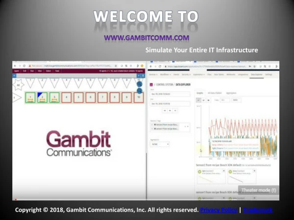
Our Professional Services support Organizations at every step of Network Connectivity by Testing and Validation. Synergix International has a wealth of experience delivering IT Professional<br>Services to major System Integrator and ICT users within the enterprise & government sectors.

E N D
Network Analyzer Basics You Need to Know WHAT IS A NETWORK ANALYZER? Synergix International network analyzers are crucial for the characterization of the devices and components used in radio frequency and microwave systems. This includes network testing for wifi, computer networks, cell phone coverage, and much more. These powerful devices are used in various stages of product development and can be used to verify the performance of various components such as antennas, amplifiers, cables, and many other active or passive devices. We use network analyzers to test these components to verify specifications of building blocks for more complex RF systems. Testing these systems ensures distortion-free transmission of communication signals and ensures a good match when absorbing power. REFLECTION MEASUREMENTS & S- PARAMETERS A network analyzer measures both magnitude and phase. Scattering parameters (S- parameters) is the method used to characterize the device and tells us the ratio of power transferred between two ports (or however many ports the device has). S- parameters have two numbers associated with them, the first number represents the port at which power is found, and the second number represents the port at which the power originated from. In a two-port network, S11 and S22 represent reflection. Reflection is a parameter that describes how much power is reflected back from the port of measurement. We can relate reflection to return loss, which is the measure of how much signal is lost when it is reflected to the source. S21 and S12 represent transmission, a measurement of the signal from one port to another. Transmission is related to insertion loss, which is the loss of signal power that results from the insertion of a device in a transmission line.
WHY MAKE REFLECTION MEASUREMENTS? Reflection measurements are made to assure the efficient transfer of power for 2 main reasons: 1. When energy is reflected, less energy is transmitted where it is intended to go, leading to the inefficient usage of very expense RF energy and resources 2. Large amounts of reflected energy can damage components such as amplifiers SMITH CHART – AN EFFECTIVE TOOL FOR RF DESIGN If you are designing a board, you can use a Smith chart to help with optimizing the DUT’s design to minimize these reflection and transmission coefficients. The Smith chart is a graphical tool for visualizing the impedance of a transmission line and antenna system as a function of frequency. You can use the Smith chart in the following applications: • Admittance/Impedance calculations on any transmission line or load • Calculation of the length of a short-circuited transmission line • Impedance matching