Download
1 / 62
640 likes | 1.06k Vues
Public Safety Radio Bands VHF-Low Band: 25 MHz to 50 MHz VHF-High: 138 MHz to 174 MHz UHF: 408 MHz to 512 MHz 700 MHz (new) 800 MHz 4.9 GHz (new) Why is this a problem? Radios only operate in one band! Multi-band radios are rare and expensive

E N D
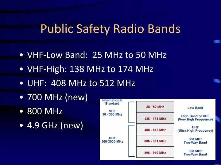
Public Safety Radio Bands • VHF-Low Band: 25 MHz to 50 MHz • VHF-High: 138 MHz to 174 MHz • UHF: 408 MHz to 512 MHz • 700 MHz (new) • 800 MHz • 4.9 GHz (new)
Why is this a problem? • Radios only operate in one band! • Multi-band radios are rare and expensive • If Agency A uses VHF and Agency B uses UHF, they can’t talk to each other UNLESS… • …They have planned ahead! • Two radios in a rig, etc.
Propagation Basics- Free Space Path Loss • Path Loss (in dB) = 20 x Log[4d/] • Where: d is distance in meters is wavelength in meters • = speed of light/frequency • So: as frequency increases, path loss increases • This means that if everything else were equal, a system at a lower frequency would reach farther than a system at a higher frequency • But…other factors are at play as well
Propagation & Band Characteristics • VHF Low Band (30-50 MHz) • Best propagation in undeveloped and hilly terrain–Poor building penetration • VHF High Band (150-174 MHz) • Very good propagation in undeveloped and hilly terrain–Moderate building penetration • UHF (450-512 MHz) • Good propagation in undeveloped and hilly terrain–Good building penetration • 700/800 MHz • Poor propagation in undeveloped and hilly terrain–Very good building penetration– • 700 currently subject to incumbent television stations in some areas • 800 currently subject to interference from commercial carriers • 4.9 GHz • Microwave propagation used for short range (Wi-Fi type) or point-to-point links
Frequencies vs. Channels • A frequency is a point in the radio spectrum • part of what describes a channel • A channel is a set of parameters that can include one or more frequencies, CTCSS tones, name, etc. • Example: VCALL is a channel with transmit and receive frequency 155.7525 MHz, CTCSS tone of 156.7 Hz
CTCSS (PL) Tones • PL stands for Private Line, a Motorola trademark • Other names include Code Guard, Tone Squelch, Call Guard, Channel Guard, Quiet Channel, Privacy Code, Sub-audible Tone, etc. • “Generic” term is CTCSS – Continuous Tone Coded Squelch System
What Are These Tones? • A PL tone is a sub-audible (barely audible) tone that is sent along with the transmitted audio • A receiver that has CTCSS decode (a.k.a. a receive PL tone) activated will only open its speaker if the correct tone is received • PL tones are different than tones used to set off pagers (two-tone sequential paging) • Remember…PL tones are sub-audible and continuous…they are being sent the entire time a radio is transmitting
What Are They Used For • PL Tones are used to MASK interference • They DO NOT REMOVE INTERFERENCE • Useful for masking interference from computers, electronics, etc. • Useful for masking interference from “skip” • Should NOT be used to block out traffic from neighboring (nearby) departments • This is OK for taxis, etc., but not for public safety • Creates “Hidden Interference” problem – missed calls possible
What Are They Used For (cont.) • Used to activate remote links • Used to access repeaters
DCS – Digital Coded Squelch • A.k.a. Digital Private Line (DPL) • Similar to CTCSS, but uses a digital code instead of an audio tone • Used on analog radio systems, even though it is a digital code
Encode vs. Decode • PL (or DPL, et.c) Encode means to transmit the tone • Decode means that the receiver will listen for the tone and not let anything through unless the correct tone is received • TX and RX tone can be different • Radio can be set to TX tone but have no RX tone (all traffic is received) • If in doubt, don’t program RX tone • “Monitor” function bypasses RX tone
Simplex • Very Reliable • Limited Range • Radio Channel uses 1 frequency
Duplex • Radio Channel using 2 frequencies, Freq 1 to talk from radio A to radio B, and Freq 2 to talk from radio B to radio A • Each user must be line of sight with each other • Examples: Cordless Telephone systems, which both parties can talk at the same time and listen at the same time. f1 f2
Base Station – Height Improves Range Dispatch Center Some units don’t hear transmission because of obstructions Unit 1 Unit 4 Unit 2 Unit 3
Base Station – Height Improves Range Dispatch Center Dispatcher relays message – heard by all units Unit 1 Unit 4 Unit 2 Unit 3
Remote Base Operation Dispatch Center Remote Link Microwave, Phone Line, etc. Unit 1 Unit 4 Unit 2 Unit 3
Conventional Repeater • Receives a signal on one frequency and retransmits (repeats) it on another frequency • Placed at a high location • Increases range of portable and mobile radio communications • Allows communication around obstructions (hills, valleys, etc.) • User radios receive on the repeaters transmit frequency and transmit on the repeater’s receive frequency (semi-duplex)
Conventional Repeater RX TX f2 f1 Dispatch Center All units within range of repeater hear all transmissions through the repeater f2 f2 f2 f2 f1 Unit 1 Unit 4 Unit 2 Repeater Unit 3
Conventional Systems When one user is talking, other users on that channel are cannot talk, even though other repeaters in the area may be idle. Communicating PD 1 PD 4 Idle PD 3 cannot talk to PD 4 because PD 1 is using the repeater PD 2 PD 3 Idle FD 3 FD 1 Public works repeater may be idle 90% of the time, which means that frequency is largely wasted PW 1 FD 2 PW 3 PW 2
Trunking • Trunking is a method of combining repeaters at the same site to “share” frequencies among users • Spectrally efficient • Allows many more “virtual” channels (called talkgroups) than there actually are frequencies • Computer controlled
PD 3 PD 1 PD 2 FD 2 FD 1 RX RX RX TX TX TX f1 f3 f5 f2 f4 f6 Trunked System f3 f1 f4 f2 f2 • Frequencies are dynamically assigned by system controller • User radio may be on a different frequency every time it transmits • Talkgroups are “virtual” channels • Possible to have many more talkgroups than actual frequencies • Statistically, not all talkgroups will be active at the same time System Controller Shared Repeater Bank
Trunked System Operation • User radios continuously monitor a dedicated “control channel” • When a user wants to transmit, the user’s radio makes a request to the system controller • If a repeater is available, the system controller temporarily assigns that repeater channel to the talkgroup making the request • Transmitting user’s radio will give a “talk beep”, indicating that a repeater has successfully been assigned…user can talk • All user radios monitoring that talkgroup automatically switch to the frequency of the assigned repeater and hear the transmission • When the transmission is complete, all radios return to monitoring the control channel
Multi-Site Systems • Conventional • Repeaters on same output, different input • Linked repeaters on different frequencies • Remote Receive Sites • Voting • Simulcasting • Trunking • Roaming • Simulcasting
Repeaters on same output frequency, different input frequency (or PL tone) Only one repeater active at a time Users must manually change channel to different repeater depending on their physical location
Repeaters on same output frequency, different input frequency (or PL tone) Only one repeater active at a time Users must manually change channel to different repeater depending on their physical location
Linked repeaters on different frequencies Both repeaters active at the same time with same traffic, but on different frequencies Link (microwave, phone line, etc.) Users must manually change channel to different repeater depending on their physical location
Voting Receivers Voter (comparator) chooses best received signal and sends that signal to the transmitter Voter Central Transmitter Link (microwave, phone line, etc.) RX Only Site Users do not need to change channel depending on location. System (voter) automatically picks best receive tower site.
Simulcasting Both repeaters transmit at the same frequency at the same time Link (microwave, phone line, etc.) Transmitters must be carefully synchronized to prevent interference in overlap areas
Common Analog Modulation Schemes • FM – Frequency Modulation • AM – Amplitude Modulation • SSB – Single Sideband AM • Almost all analog public safety communications use FM • AM is used for CB radio, aircraft communication
Frequency Modulation (FM) • To modulate means “to change” or “to vary” • Frequency Modulation means changing the frequency of the transmitter in proportion to the audio being picked up by the microphone • The receiver detects the change in transmitter frequency and uses it to reproduce the audio signal at the speaker
Frequency Modulation – An Illustration Microphone Output: Transmitter Output:
FM Radio Block Diagrams(simplified) Transmitter Receiver
Digital Modulation • Signal from microphone is converted from a voltage into numbers through a process called sampling • Those numbers are processed by a computer • Binary information (ones and zeros) is sent over the air instead of analog (continuous voltage) information
Frequency Shift Keying – An Illustration Digital Bitstream: Transmitter Output:
Vocoding • Vocoding is used to reduce the amount of data that needs to be sent over the air • Used to reduce necessary bandwidth – conserves spectrum • “Compresses” digital audio – analogous to .mp3 versus .wav audio files • Uses known human speech characteristics to “fill in gaps” of data that is removed
Digital Radio Block Diagrams(simplified) Transmitter Receiver
The Digital Radio “Problem” • Parametric vocoder uses known human voice characteristics to encode and decode data • When background noise (non-human noise) is present, vocoder doesn’t always know how to respond • Unpredictable results (garble, loss of communication, etc.) • In a similar situation, an analog radio would transmit the background noise right along with the intended audio (background noise might overpower voice, but some audio is still received)
Possible Permutations • VHF Analog Conventional Simplex • UHF Analog Conventional Simplex • 800 MHz Analog Conventional Simplex • VHF Analog Conventional Repeater • UHF Analog Conventional Repeater • 800 MHz Analog Conventional Repeater • VHF Digital Conventional Simplex • UHF Digital Conventional Simplex • 800 MHz Digital Conventional Simplex • VHF Digital Conventional Repeater • UHF Digital Conventional Repeater • VHF Analog Trunking Repeater (very rare) • UHF Analog Trunking Repeater (rare for public safety) • 800 MHz Analog Trunking Repeater • VHF Digital Trunking Repeater • UHF Digital Trunking Repeater • 800 MHz Digital Trunking repeater
What is Narrowbanding? • Effort by FCC to increase the number of useable radio channels below 512 MHz • Advances in technology allow signals to take up less bandwidth than in the past • Regulations are changing to take advantage of new technologies • Starting 2013, all radio systems must be narrowband compliant
What is Narrowbanding? (cont.) • Splits 25 kHz wide channel into two 12.5 kHz wide channels • When technology permits, there will be another migration to 6.25 kHz technology • For FM (analog) systems, narrowbanding is accomplished by reducing the transmitter’s FM deviation – receiver must compensate on the other end
20KHz Bandwidth 20KHz Bandwidth 20KHz Bandwidth Existing VHF Systems:Already a problem. Not able to use adjacent channels at close distances. WideBand WideBand WideBand Overlap Overlap Adjacent channels 15KHz Channel Spacing 15KHz Channel Spacing 155.760 155.745 155.775 Joe Kuran Oregon SIEC
After Narrowband:Still a problemNarrowband channels not usable until wideband users vacate. 20KHz Bandwidth 20KHz Bandwidth Wide Band Wide Band 20KHz Bandwidth Overlap Overlap Wide Band ANALOG NARROWBAND ANALOG NARROWBAND 7.5KHz Channel Spacing 11KHz Bandwidth 155.745 155.775 155.760 155.7525 155.7675 Joe Kuran Oregon SIEC
After all convert to NarrowbandStill some overlay with analog modulation This represents analog voice with a 11KHz necessary bandwidth ANALOG NARROWBAND ANALOG NARROWBAND ANALOG NARROWBAND ANALOG NARROWBAND ANALOG NARROWBAND 7.5KHz Channel Spacing 11KHz Bandwidth 155.745 155.775 155.760 155.7525 155.7675 Joe Kuran Oregon SIEC
Convert to Project 25 DigitalPhase I Digital Modulation allows tighter packing of channels Still a very minor overlay in the VHF band. UHF band will have no overlay because of 12.5KHz Channel Spacing. P25 with C4FM Modulation only requires 8.1KHz Necessary Bandwidth DIGITAL NARROWBAND DIGITAL NARROWBAND DIGITAL NARROWBAND DIGITAL NARROWBAND DIGITAL NARROWBAND 8.1KHz Bandwidth 7.5KHz Channel Spacing 155.745 155.775 155.760 155.7525 155.7675 Joe Kuran Oregon SIEC
What Do I Need to Do? • Update FCC License • Obtain narrowband-capable radios • Program all radios for narrowband operation (at the same time) • DOES NOT require moving to 800 MHz or digital (although those are options)
Why New Radios? • Narrowbanding halved a frequency’s bandwidth and deviation. • Many older wideband radios will not operate on frequencies set 12.5kHz apart (154.XXXX instead of 154.XXX) • An older wideband radio’s bandwidth is 25kHz. This would interfere with both new 12.5kHz narrowband frequencies on either side of the old 25kHz frequency. • An older wideband radio’s deviation is 5kHz. New narrowband radios will respond to this signal by either: • Not process the wideband deviation into a received audio signal. • Process it into a bad received audio signal (garbled, distorted, etc.).