Download
1 / 58
600 likes | 1.73k Vues
5. The Processor: Datapath and Control The Processor: Datapath & Control We're ready to look at an implementation of the MIPS Simplified to contain only: memory-reference instructions: lw, sw arithmetic-logical instructions: add, sub, and, or, slt control flow instructions: beq, j

E N D
5. The Processor: Datapath and Control 순천향대학교 정보기술공학부 이 상 정 1
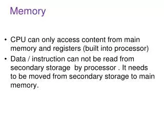
The Processor: Datapath & Control • We're ready to look at an implementation of the MIPS • Simplified to contain only: • memory-reference instructions: lw, sw • arithmetic-logical instructions: add, sub, and, or, slt • control flow instructions: beq, j • Generic Implementation: • use the program counter (PC) to supply instruction address • get the instruction from memory • read registers • use the instruction to decide exactly what to do • All instructions use the ALU after reading the registers Why? memory-reference? arithmetic? control flow? 순천향대학교 정보기술공학부 이 상 정 2
More Implementation Details • Abstract / Simplified View:Two types of functional units: • elements that operate on data values (combinational) • elements that contain state (sequential) 순천향대학교 정보기술공학부 이 상 정 3
State Elements • Unclocked vs. Clocked • Clocks used in synchronous logic • when should an element that contains state be updated? cycle time 순천향대학교 정보기술공학부 이 상 정 4
An unclocked state element • The set-reset latch • output depends on present inputs and also on past inputs 순천향대학교 정보기술공학부 이 상 정 5
Latches and Flip-flops • Output is equal to the stored value inside the element (don't need to ask for permission to look at the value) • Change of state (value) is based on the clock • Latches: whenever the inputs change, and the clock is asserted • Flip-flop: state changes only on a clock edge (edge-triggered methodology) "logically true", — could mean electrically low A clocking methodology defines when signals can be read and written — wouldn't want to read a signal at the same time it was being written 순천향대학교 정보기술공학부 이 상 정 6
D-latch • Two inputs: • the data value to be stored (D) • the clock signal (C) indicating when to read & store D • Two outputs: • the value of the internal state (Q) and it's complement 순천향대학교 정보기술공학부 이 상 정 7
D flip-flop • Output changes only on the clock edge 순천향대학교 정보기술공학부 이 상 정 8
Our Implementation • An edge triggered methodology • Typical execution: • read contents of some state elements, • send values through some combinational logic • write results to one or more state elements 순천향대학교 정보기술공학부 이 상 정 9
Register File • Built using D flip-flops Do you understand? What is the “Mux” above? 순천향대학교 정보기술공학부 이 상 정 10
Abstraction • Make sure you understand the abstractions! • Sometimes it is easy to think you do, when you don’t 순천향대학교 정보기술공학부 이 상 정 11
Register File • Note: we still use the real clock to determine when to write 순천향대학교 정보기술공학부 이 상 정 12
Elements for Instruction Fetch • Basic Instruction Fetch Unit 순천향대학교 정보기술공학부 이 상 정 13
Elements for R-format Instructions /Load/Store Instuctions • Two elements for R-format • R[rd] <- R[rs] op R[rt] • Additional elements for Load/Store • R[rt] <- Mem[R[rs] + SignExt[imm16]] 순천향대학교 정보기술공학부 이 상 정 14
Datapath for a Branch • If (R[rs] == R[rt]) PC <- PC + 4 + ( SignExt(imm16) x 4 ) Else PC <- PC + 4 순천향대학교 정보기술공학부 이 상 정 15
Datapath for Lw/Sw and R-type 순천향대학교 정보기술공학부 이 상 정 16
Putting it Altogether 순천향대학교 정보기술공학부 이 상 정 17
Control • Selecting the operations to perform (ALU, read/write, etc.) • Controlling the flow of data (multiplexor inputs) • Information comes from the 32 bits of the instruction • Example: add $8, $17, $18 000000 10001 10010 01000 00000 100000 op rs rt rd shamt funct • ALU's operation based on instruction type and function code 순천향대학교 정보기술공학부 이 상 정 18
op(6) rs(5) rt(5) rd(5) shamt(5)func(6) op(6) rs(5) rt(5) 16 bit address op(6) 26 bit address Three Instruction Classes • op. 6 bits and funct. 6 bits can be used to generate control signals • I-type an J-type instructions only have op. 6 bits • R-type instructions have both op. 6 bits and funct. 6 bits R I J 순천향대학교 정보기술공학부 이 상 정 19
ALU Control • e.g., what should the ALU do with this instruction • Example: lw $1, 100($2) 35 2 1 100 op rs rt 16 bit offset • ALU control input0000 AND 0001 OR 0010 add 0110 subtract 0111 set-on-less-than1100 NOR 순천향대학교 정보기술공학부 이 상 정 20
RegDst Big Single Control Logic (becomes slow) Branch op MemRead 6 MemtoReg RegWrite func MemWrite 6 ALUSrc ALUctr 4 func ALUctr Small Control 2 (fast) op 6 Small Control 1 (fast) 4 ALUop 6 2 RegDst Branch MemRead MemtoReg RegWrite MemWrite ALUSrc Control with Local Decoding ALU Control Main Control 순천향대학교 정보기술공학부 이 상 정 21
ALU Control (ALUctr) 순천향대학교 정보기술공학부 이 상 정 22
Truth Table for ALU Control • Can turn into gates: 순천향대학교 정보기술공학부 이 상 정 23
Control for R-type Instruction • Data path and active control signals are highlighted 순천향대학교 정보기술공학부 이 상 정 24
Control for “load” instruction 순천향대학교 정보기술공학부 이 상 정 25
Control for “branch equal” 순천향대학교 정보기술공학부 이 상 정 26
Truth Table for Main Control 순천향대학교 정보기술공학부 이 상 정 28
Control • Simple combinational logic (truth tables) 순천향대학교 정보기술공학부 이 상 정 29
Implementing Jump j Exit op Exit (26 bit address) $pc xxxx xxxx Exit (26 bit address) 00 jump addr. 순천향대학교 정보기술공학부 이 상 정 30
Our Simple Control Structure • All of the logic is combinational • We wait for everything to settle down, and the right thing to be done • ALU might not produce “right answer” right away • we use write signals along with clock to determine when to write • Cycle time determined by length of the longest path We are ignoring some details like setup and hold times 순천향대학교 정보기술공학부 이 상 정 31
Performance of Single Cycle Datapath • Calculate cycle time assuming negligible delays except: • memory (200ps), ALU and adders (100ps), register file access (50ps) • Minimum Cycle Time > 600ps! 순천향대학교 정보기술공학부 이 상 정 32
Where we are headed • Single Cycle Problems: • what if we had a more complicated instruction like floating point? • wasteful of area • One Solution: • use a “smaller” cycle time • have different instructions take different numbers of cycles • a “multicycle” datapath: 순천향대학교 정보기술공학부 이 상 정 33
What’s wrong with our CPI=1 processor? Arithmetic & Logical PC Inst Memory Reg File ALU setup mux mux Load PC Inst Memory Reg File ALU Data Mem setup mux mux Critical Path Store PC Inst Memory Reg File ALU Data Mem mux Branch PC Inst Memory Reg File cmp mux • Long Cycle Time • All instructions take as much time as the slowest • Real memory is not so nice as our idealized memory • cannot always get the job done in one (short) cycle 순천향대학교 정보기술공학부 이 상 정 34
storage element storage element Combinational Logic (A) Combinational Logic storage element Combinational Logic (B) storage element storage element Reducing Cycle Time • Cut combinational dependency graph and insert register / latch • Do same work in two fast cycles, rather than one slow one => 순천향대학교 정보기술공학부 이 상 정 35
Partitioning the CPI=1 Datapath Add registers between smallest steps MemWr MemRd RegWr RegDst nPC_sel ALUSrc ExtOp ALUctr Reg. File Operand Fetch Exec Instruction Fetch Mem Access PC Next PC 순천향대학교 정보기술공학부 이 상 정 36
Example Multicycle Datapath MemToReg RegWr RegDst MemWr MemRd nPC_sel ALUctr ALUSrc ExtOp Reg. File Ext ALU A Reg File S PC IR Next PC B Mem Access M Instruction Fetch Result Store Operand Fetch 순천향대학교 정보기술공학부 이 상 정 37
inst Physical Register Transfers IR <– MEM[pc] ADD A<– R[rs]; B <– R[rt] S <– A + B R[rd] <– S; PC <– PC + 4 A S B M R-rtype (add, sub, . . .) inst Logical Register Transfers ADD R[rd] <– R[rs] + R[rt]; PC <– PC + 4 • Logical Register Transfer • Physical Register Transfers Reg. File Reg File Exec PC IR Next PC Inst. Mem Mem Access 순천향대학교 정보기술공학부 이 상 정 38
inst Physical Register Transfers IR <– MEM[pc] LW A<– R[rs]; B <– R[rt] S <– A + SignEx(Im16) M <– MEM[S] R[rt] <– M; PC <– PC + 4 A S B M Reg. File Reg File Exec PC IR Next PC Inst. Mem Mem Access Load • Physical Register Transfers • Logical Register Transfer inst Logical Register Transfers LW R[rt] <– MEM(R[rs] + sx(Im16); PC <– PC + 4 순천향대학교 정보기술공학부 이 상 정 39
A S B M Store • Logical Register Transfer • Physical Register Transfers inst Physical Register Transfers IR <– MEM[pc] SW A<– R[rs]; B <– R[rt] S <– A + SignEx(Im16); MEM[S] <– B PC <– PC + 4 inst Logical Register Transfers SW MEM(R[rs] + sx(Im16) <– R[rt]; PC <– PC + 4 Reg. File Reg File Exec PC IR Next PC Inst. Mem Mem Access 순천향대학교 정보기술공학부 이 상 정 40
S M Branch • Physical Register Transfers • Logical Register Transfer inst Physical Register Transfers IR <– MEM[pc] BEQ A<– R[rs]; B <– R[rt] S <– A - B Eq:PC<-PC+4+sx(Im16)||00, ~Eq:PC <– PC + 4 inst Logical Register Transfers BEQ if R[rs] == R[rt] then PC <= PC + 4 + sx(Im16) || 00 else PC <= PC + 4 Equal Reg. File Reg File A Exec IR PC Inst. Mem Next PC B Mem Access 순천향대학교 정보기술공학부 이 상 정 41
Summary: 순천향대학교 정보기술공학부 이 상 정 42
PCWr PCWrCond PCSrc 32 Zero ALUSelA IorD MemWr IRWr RegDst RegWr 1 0 Mux Mux 32 PC 1 0 0 Zero 32 Rs Mux Ra 0 32 32 RAdr 5 32 S 1 Rt busA A Mux Rb ALU Control 32 Mux ALU 1 0 Ideal Memory 32 Instruction Reg Reg File << 2 5 1 4 0 Rw 32 WrAdr 32 5 busB B 1 32 Rd Din Dout busW Extend 2 16 32 3 M Imm 32 ALUOp ExtOp MemtoReg ALUSelB Multiple Cycle Datapath • Miminizes Hardware: 1 memory, 1 adder 순천향대학교 정보기술공학부 이 상 정 43
Multi-Cycle Datapath & Control Signals • Figure 5.28 in page 323 순천향대학교 정보기술공학부 이 상 정 44
start Instruction fetch / decode and register fetch Memory access instructions R-type instructions Branch instructions Jump instruction High-Level Control Flow • Common 2-clock sequence to fetch/decode any instruction • Separate sequences of 1 to 3 clocks to execute specific types of instruction • Two techniques for control • finite state machine • microprogramming 순천향대학교 정보기술공학부 이 상 정 45
Next-state function Current state clock Inputs Output function Outputs Review of Finite State Machine(FSM) • Finite state machine • a set of states and • next state function (determined by current state and input) • output function (determined by current state and input) • We will use a Moore machine • output based only on current state • cf. Mealy machine: output based on both current state and input 순천향대학교 정보기술공학부 이 상 정 46
Control Finite State Machine(FSM) Diagram 순천향대학교 정보기술공학부 이 상 정 47
Combinational Control Logic (random logic or PLA) outputs Datapath control outputs inputs Next state inputs from instruction register opcode field State register Control Finite State Machine Structure • Outputs to datapath control determined by current state • Next state determined by current state and input from instruction register 순천향대학교 정보기술공학부 이 상 정 48
AND plane OP code current state OR plane PLA Implementation 순천향대학교 정보기술공학부 이 상 정 49
Microprogramming • Microprogramming is an alternate structure for implementing the control finite state machine • represent outputs and next state selection as microinstructions in a memory (the control store) addressed by the current state (often called the microprogram counter) • the control store can be implemented in ROM or RAM (writable control store) • provides level of abstraction between software and datapath hardware: firmware 순천향대학교 정보기술공학부 이 상 정 50