Download
1 / 46
460 likes | 808 Vues
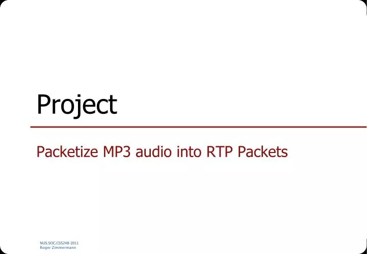
Project. Packetize MP3 audio into RTP Packets. Goals (1). Encode audio into streamable MP3 format according to RFC 2250 and RFC 5219. Use the Yima Personal Edition (Yima PE) streaming media server code, running under Linux .

E N D
Project Packetize MP3 audio into RTP Packets
Goals (1) • Encode audio into streamable MP3 format according to RFC 2250 and RFC 5219. • Use the Yima Personal Edition (Yima PE) streaming media server code, running under Linux. • (1) Modify the yimasplit utility, which creates data blocks containing pre-computed RTP packets with appropriate RTP headers.
Goals (2) • Server reads data blocks, schedules and sends out RTP packets. • (2) Modify the Yima PE MP3 Player client to accept, de-packetize and play audio. This player works under Windows. • (3) Design experiments to show the benefits of RFC 5219 over RFC 2250. Use a packet loss model to simulate congestion.
Project Homepage • Descriptions • Yima Personal Edition Source Codes • Documentation (RFCs, etc.) • IVLE Forums • TA: Shen Zhijie
Advice • Form team (1 or 2 persons). • Note: The Yima PE source code is not very well documented. • Start early!
Introduction to Yima PE Personal Edition Streaming Media System
Overview # ./yimaserver <YimaPE 1.0> begin scheduler <YimaPE 1.0> begin rtsps • Command line server • GUI client • “Split” utility to prepare media files • RTSP communication (port 5xxxx)
Software Source • Directories • ServerServer code • Client Client code and GUI library • Splitter Media preparation utility • Streams Sample media (WAV file) • Remove all object files (*.o) before building the executables
Yima PE Server • RTSP front and backend (one process) • Scheduler + FLIB (one process) • Qpthread v1.3.1 library for multi-threading • Must set LP_LIBRARY_PATH to include Qpthread • Server configuration file: config • Where are the media files located • Name, size [bytes] and duration [sec]
Splitter • Input: yimaintro.wav (for example) • Output: BLOCKS sub-directory • Data block files: yimaintro.wav_1, yimaintro.wav_2, … • Each block is 256,000 bytes and contains 500 RTP packets (of 512 bytes each) • A sample config file is created; must copy contents to the main config file
Server + Splitter • Server does not care about block contents, i.e., it does not know what kind of media data is stored (MPEG-1/2, WAVE, …) • Server sends RTP packets based on config info: • BW = size / duration • Packet-level scheduling • Need only modify splitter for MP3 media!
Linux Client • Operation: • [List] button: reads mediaentries from local Yima.cfg file • [Play], [Pause], [Stop] buttons execute RTSP commands to server • GUI was built with XForms library; it is message-driven, with callback functions for buttons, etc. Plays uncompressed audio (PCM).
Windows Client • Operation: • [List] button: reads mediaentries from local Yima.cfg file • [Play], [Pause], [Stop] buttons execute RTSP commands to server • GUI was built with Visual Studio C/C++ (MFC library); it is message-driven, with callback functions for buttons. Includes MP3 decoder.
Client Structure Player “P” • 3 threads • Statemachine GUI “C” /dev/dsp Buffer Network “N” RTP CommandMessage Queues, e.g., put_cmd(CtoN, …); RTSP
Continuous Media Servers • Introduction • Continuous Media • Magnetic Disk Drives • Display of CM (single disk, multi-disks ) • Optimization Techniques • Additional Issues • Case Study (Yima)
What is a CM Server? Network Storage Manager • Multiple streams of audio and video should be delivered to many users simultaneously. Memory
Video-on-demand News-on-demand News-editing Movie-editing Interactive TV Digital libraries Distance Learning Medical databases NASA databases Some Applications
Continuous Display • Data should be transferred from the storage device to the memory (or display) at a pre-specified rate. • Otherwise: frequent disruptions & delays, termed hiccups. • NTSC quality: 270 Mb/s uncompressed; 3-8 Mb/s compressed (MPEG-2). Memory Disk
Challenge: Real-Time Media • Bandwidth requirements for different media types: 100 Mb/s 50 Mb/s 31 Mb/s 20 Mb/s 4-6 Mb/s 1 Mb/s
HDTV quality ~ 1.4 Gb/sUncompressed!Standard: SMPTE 292M 2-hr HDTV ~ 1260 GB High Bandwidth & Large Size
Streaming Media Servers • Streaming media servers require a different “engine” than traditional databases because of: • Real-time retrieval and storage • Large media objects • The performance metrics for streaming media servers are: • The number of simultaneous displays: throughput N • The amount of time that elapses until a display starts: startup latency L • The overall cost of the system: cost per stream, C
Media Types • Examples of continuous media are: • Audio • Video • Haptics • Continuous media are often compressed. There are many different compression algorithms, for example: • Motion Picture Experts Group: MPEG-1, MPEG-2, MPEG-4 • Joint Photographic Expert Group: Motion-JPEG • Digital Video: DV, MiniDV • Microsoft Video 9, DivX, … • MP3: MPEG-1 layer 3 audio • Above codecs are based ondiscrete cosine transform (DCT) Others: • Wavelet-based codecs • Lossless compression
Compression • MPEG-1 180:1 reduction in both size and bandwidth requirement (SMPTE 259M, NTSC 270 Mb/s is reduced to 1.5 Mb/s). • MPEG-2 30:1 to 60:1 reduction.(NTSC ~ 4, DVD ~ 8, HDTV ~ 20 Mb/s) • Problem: loose information(cannot be tolerated by some applications: medical, NASA)
Media Characteristics • Data requires a specific bandwidth: • Constant bitrate (CBR) CM • Variable bitrate (VBR) CM • Easier case: CBR • Data is partitioned into equi-sized blocks which represent a certain display time of the media • E.g.: 176,400 bytes represent 1 second of playtime for CD audio (44,100 samples per second, stereo, 16-bits per sample)
Assumed Hardware Platform • Multiple magnetic disk drives: • Not too expensive(as compared to RAM) • Not too slow(as compared to tape) • Not too small(as compared to CD-ROM) • And it’s already everywhere! Memory
Magnetic Disk Drives • An electro-mechanical random access storage device • Magnetic head(s) read and write data from/to the disk Disk Drive Internals
Disk Seek Time Model If d < z cylinders If d >= z cylinders
Disk Service Time • The disk service time is dependent on several factors: • Seek time • Platter diameter (e.g., 3.5”, 2.5”, 1”) • Rotational latency • Spindle speed • Data transfer time • Zone-bit recording • Read versus write bandwidth
Disk Service Time Model • TTransfer: data transfer time [s] • TAvgRotLatency: average rotational latency [s] • TService: service time [s] • B: block size [MB] • BWEffective: effective bandwidth [MB/s]
Sample Calculations • Assumptions: • TSeek = 10 ms • BWMax = 20 MB/s • Spindle speed: 10,000 rpm
Summary • Average rotational latency depends on the spindle speed of the disk platters (rpm). • Seek time is a non-linear function of the number of cylinders traversed. • Average rotational latency + seek time = overhead (wasteful). • Average rotational latency and seek time reduce the maximum bandwidth of a disk drive to the effective bandwidth
Continuous Display (1 disk) Retrieve from disk X2 X3 X1 Display from memory Display X1 Display X2 Display X3 Time • Traditional production/consumption problem • RC = Consumption Rate, e.g., MPEG-1: 1.5 Mb/s. • RD = Production Rate, Seagate Cheetah X15: 40-55 MB/s. • For now: RC < RD • Partition video X into n blocks: X1, X2, ..., Xn(to reduce the buffer requirement)
Round-robin Display Retrieve from Disk X2 X3 X1 Y3 Y4 Y5 Seek Time Display from Memory Display X1 Display X2 Display X3 Display Y3 Display Y4 Display Y5 Time • Time period: time to display a block (is fixed). • System Throughput (N): number of streams. • Assuming random assignment of the blocks: • Maximum seek time between block retrievals • Waste of disk bandwidth ==> lower throughput • Tp=?, N=?, Memory=?, max-latency=?
Y5 Cycle-based Display Retrieve from Disk Z5 Z6 X2 X3 Z7 X1 Y3 Y4 Display from Memory Display X1, Y3, Z5 Display X2, Y4, Z6 Time • Using disk scheduling techniques • Less seek time ==> Less disk bandwidth waste ==> Higher throughput • Larger buffer requirement • Tp=?, N=?, Memory=?, max-latency=?
Y5 Group Sweeping Schema (GSS) Group 1 Group 2 Z5 X2 Z6 X3 Z7 W1 X1 Y3 W2 Y4 W3 Subcycle 1 Subcycle 2 Display X1, W1 Display X2, W2 • Can shuffle order of blocks retrievals within a group • Cannot shuffle the order of groups • GSS when g=1 is cycle-based • GSS when g=N is round-robin • Optimal value of g can be determined to minimize memory buffer requirements • Tp=?, N=?, Memory=?, max-latency=?
System Issues • Movie is cut into equi-sized blocks: X0, X1, …, Xn-1. • Time required to display one block is called time period Tp. • Note: Tp is usually longer than the disk retrieval time of a block; this allows multiplexing of a disk among different displays. Server Retrieval Time X0 X1 X2 Network X0 X1 X2 Buffer X0 X1 Buffer empty Display X0 X1 X2 Time period Hiccup
Constrained Data Placement • Partition the disk into R regions. • During each time period only blocks reside in the same region are retrieved. • Maximum seek time is reduced almost by a factor of R. • Introduce startup latency time • Tp=?, N=?, Memory=?, max-latency=?
Hybrid • For the blocks retrieved within a region, use GSS schema. • This is the most general approach; • Tp=?, N=?, Memory=?, max-latency=? • By varying R and g all the possible display techniques can be achieved. • Round-robin (R=1, g=N). • Cycle-based (R=1, g=1). • Constrained placement (R>0, g=1), ... • A configuration planner calculates the optimal values of R & g for certain application.
Display of Mix of Media Retrieve from Disk Z5 Z6 X2 X3 Z7 X1 Y3 Y4 Y5 Display from Memory Display X1, Y3, Z5 Display X2, Y4, Z6 Time • Mix of media types: different RC’s: audio, video;e.g.: Rc(Y) < Rc(X) < Rc(Z) • Different block sizes: Rc(X)/B(X)=Rc(Y)/B(Y)= ... • Display time of a block (time period) is still fixed.
Multiple-disks • Single disk: even in the best case with 0 seek time, 240/1.5 = 160 MPEG-1 streams. • Typical applications (MOD): 1000’s of streams. • Solution: aggregate bandwidth and storage space of multiple disk drives. • How to place a video? Memory
RAID Striping • All disks take part in the transmission of a block. • Can be conceptualized as a single disk. • Even distribution of display load. • Efficient admission. • Is not scalable in throughput. X1 d1 d2 d3 X1.1 X1.2 X1.3 X2.1 X2.2 X2.3
Round-robin Retrieval d1 d2 d3 • Only a single disk takes part in the transmission of each block. • Retrieval schedule • Round-robin retrieval of the blocks. • Even distribution of display load. • Efficient admission. • Not scalable in latency. X1 X2 X3 W1 Y2 Y3 Y1 Z1 Z2 W2 W3 Z3 Retrieval Schedule d1 d2 d3 Display Time X1,Y1,W1,Z1 X2,Y2,W2,Z2 X3,Y3,W3,Z3
Hybrid Striping • Partition D disks into clusters of d disks. • Each block is declustered across the d disks that constitute a cluster (each cluster is a logical disk drive). • RAID striping within a cluster. • Round-robin retrieval across the clusters. • RAID striping (d=D), Round-robin retrieval (d=1).