Download
1 / 6
60 likes | 67 Vues
https://www.irjet.net/archives/V6/i11/IRJET-V6I1104.pdf

E N D
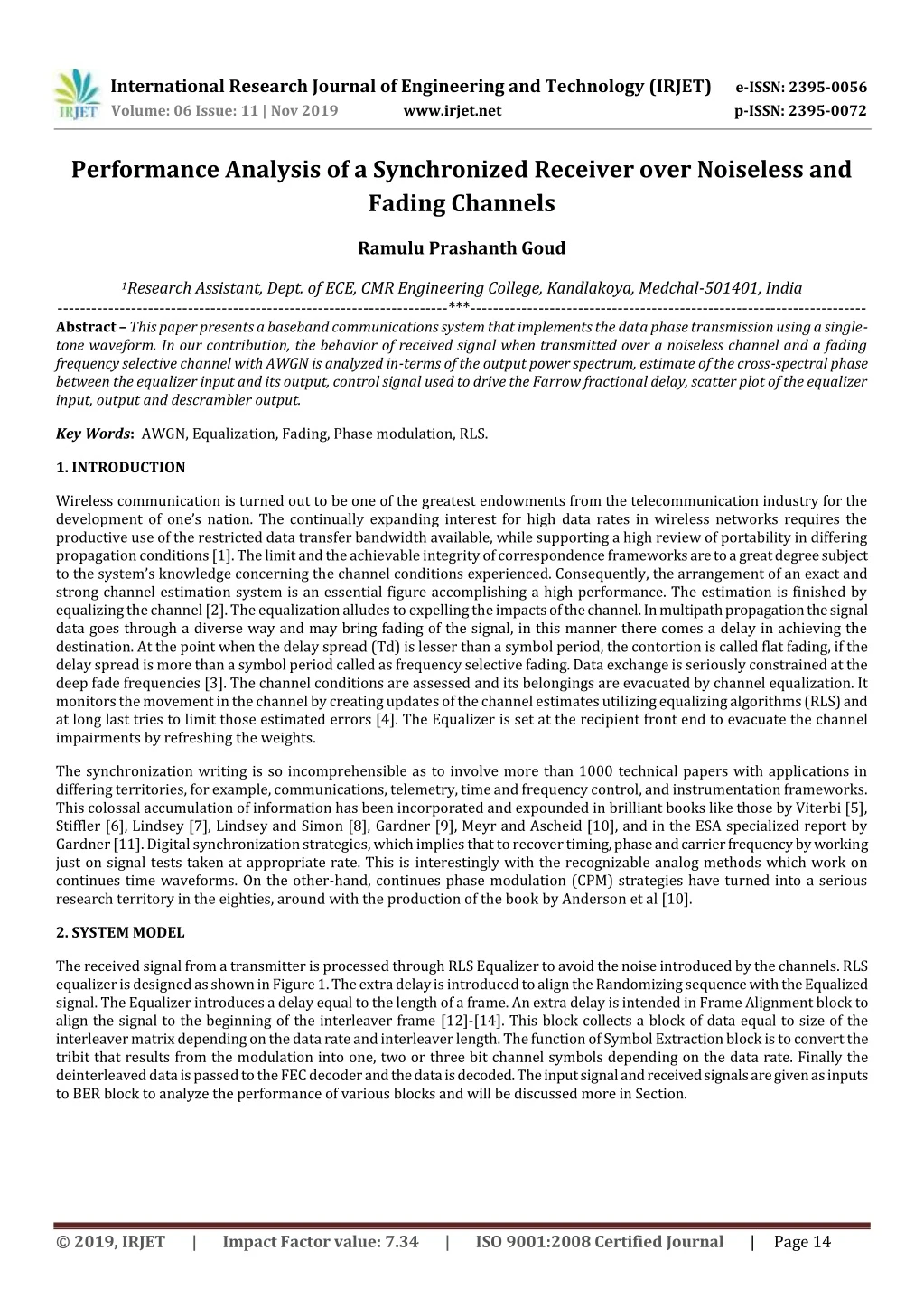
International Research Journal of Engineering and Technology(IRJET) e-ISSN: 2395-0056 Volume: 06 Issue: 11 | Nov 2019 www.irjet.net p-ISSN: 2395-0072 Performance Analysis of a Synchronized Receiver over Noiseless and Fading Channels Ramulu Prashanth Goud 1Research Assistant, Dept. of ECE, CMR Engineering College, Kandlakoya, Medchal-501401, India ---------------------------------------------------------------------***---------------------------------------------------------------------- Abstract –This paper presents a baseband communications system that implements the data phase transmission using a single- tone waveform. In our contribution, the behavior of received signal when transmitted over a noiseless channel and a fading frequency selective channel with AWGN is analyzed in-terms of the output power spectrum, estimate of the cross-spectral phase between the equalizer input and its output, control signal used to drive the Farrow fractional delay, scatter plot of the equalizer input, output and descrambler output. Key Words: AWGN, Equalization, Fading, Phase modulation, RLS. 1. INTRODUCTION Wireless communication is turned out to be one of the greatest endowments from the telecommunication industry for the development of one’s nation. The continually expanding interest for high data rates in wireless networks requires the productive use of the restricted data transfer bandwidth available, while supporting a high review of portability in differing propagation conditions [1]. The limit and the achievable integrity of correspondence frameworks are to a great degree subject to the system’s knowledge concerning the channel conditions experienced. Consequently, the arrangement of an exact and strong channel estimation system is an essential figure accomplishing a high performance. The estimation is finished by equalizing the channel [2]. The equalization alludes to expelling the impacts of the channel. In multipath propagation the signal data goes through a diverse way and may bring fading of the signal, in this manner there comes a delay in achieving the destination. At the point when the delay spread (Td) is lesser than a symbol period, the contortion is called flat fading, if the delay spread is more than a symbol period called as frequency selective fading. Data exchange is seriously constrained at the deep fade frequencies [3]. The channel conditions are assessed and its belongings are evacuated by channel equalization. It monitors the movement in the channel by creating updates of the channel estimates utilizing equalizing algorithms (RLS) and at long last tries to limit those estimated errors [4]. The Equalizer is set at the recipient front end to evacuate the channel impairments by refreshing the weights. The synchronization writing is so incomprehensible as to involve more than 1000 technical papers with applications in differing territories, for example, communications, telemetry, time and frequency control, and instrumentation frameworks. This colossal accumulation of information has been incorporated and expounded in brilliant books like those by Viterbi [5], Stiffler [6], Lindsey [7], Lindsey and Simon [8], Gardner [9], Meyr and Ascheid [10], and in the ESA specialized report by Gardner [11]. Digital synchronization strategies, which implies that to recover timing, phase and carrier frequency by working just on signal tests taken at appropriate rate. This is interestingly with the recognizable analog methods which work on continues time waveforms. On the other-hand, continues phase modulation (CPM) strategies have turned into a serious research territory in the eighties, around with the production of the book by Anderson et al [10]. 2. SYSTEM MODEL The received signal from a transmitter is processed through RLS Equalizer to avoid the noise introduced by the channels. RLS equalizer is designed as shown in Figure 1. The extra delay is introduced to align the Randomizing sequence with the Equalized signal. The Equalizer introduces a delay equal to the length of a frame. An extra delay is intended in Frame Alignment block to align the signal to the beginning of the interleaver frame [12]-[14]. This block collects a block of data equal to size of the interleaver matrix depending on the data rate and interleaver length. The function of Symbol Extraction block is to convert the tribit that results from the modulation into one, two or three bit channel symbols depending on the data rate. Finally the deinterleaved data is passed to the FEC decoder and the data is decoded. The input signal and received signals are given as inputs to BER block to analyze the performance of various blocks and will be discussed more in Section. © 2019, IRJET | Impact Factor value: 7.34 | ISO 9001:2008 Certified Journal | Page 14
International Research Journal of Engineering and Technology(IRJET) e-ISSN: 2395-0056 Volume: 06 Issue: 11 | Nov 2019 www.irjet.net p-ISSN: 2395-0072 Figure 1: RLS Equalizer. 3. NUMERICAL ANALYSIS In basic linear model, let us consider estimation of vector θ in model that is linear inθ. Classical linear form can be defined as (1) where Yi is i th measurement, hiis corresponding “design vector,” and ni is unknown noise value. This model is used extensively in control, statistics, signal processing, etc. However, many estimation/optimization criteria based on “squared- error"-type loss functions which leads to criteria that are quadratic in θ and Unique (global) estimate θ. This Criterion (loss function) has form (2) ] and Hk is k × p concatenated matrix of hT where Yk = [y1,y2,....,yi i row vectors. Classical batch least-squares estimate is (3) Popular recursive estimates (LMS, RLS, Kalman filter) may be derived from batch estimate. However, batch form may not be convenient in many applications, for example, data arrive over time and want “easy” way to update estimate at time i to estimate at time k+1. Least-mean-squares (LMS) method is very popular recursive method which is a Stochastic analogue of steepest descent algorithm and LMS recursion can be written as (4) Suppose process is modeled according to autoregressive (AR) form: © 2019, IRJET | Impact Factor value: 7.34 | ISO 9001:2008 Certified Journal | Page 15
International Research Journal of Engineering and Technology(IRJET) e-ISSN: 2395-0056 Volume: 06 Issue: 11 | Nov 2019 www.irjet.net p-ISSN: 2395-0072 (5) where xi represents state, γ and αi are unknown parameters, ui is control, and ni is noise. Let target (“desired”) value for xi be di, Optimal control law known (minimizes mean-square tracking error) as (6) An alternative to LMS is Recursive Least Squares (RLS) which is a stochastic analogue of Newton-Raphson (“second order” method) and faster convergence than LMS in practice. The two recursions of RLS algorithm are (7) It is common to have the underlying true θ evolve in time (e.g., target tracking, adaptive control, sequential experimental design, etc.). Prototype recursive form for estimating θi is (8) where choice of Ai and Ii depends on specific algorithm. 4. RESULTS AND DISCUSSION The full receiver which shown in Figure 2 mainly comprises of four blocks such as Acquired Passband Waveform, Frequency Translator and Channel, Receiver and Byte Error display [15], and the internal operations of the receiver is shown in Figure 3. Figures 4, 5 show the behavior of received signal when transmitted over a noiseless channel and a fading frequency selective channel with AWGN, respectively. Figure 4 depicts the plots for a noiseless channel (a) The channel output power spectrum (b) Estimate of the cross-spectral phase between the equalizer input and its output (c) Control signal used to drive the Farrow fractional delay (d) Scatter plot of the equalizer input (e) Equalizer output (f) Descrambler output. It can be observed that a distortion in the signal due to the effect of the noise in the fading channel [15] - [20]. Figure 2: Basic block diagram of receiver. Figure 3: Synchronization operations involved in receiver. © 2019, IRJET | Impact Factor value: 7.34 | ISO 9001:2008 Certified Journal | Page 16
International Research Journal of Engineering and Technology(IRJET) e-ISSN: 2395-0056 Volume: 06 Issue: 11 | Nov 2019 www.irjet.net p-ISSN: 2395-0072 Figure 4: Plots for a noiseless channel (a)The channel output power spectrum (b)Estimate of the cross-spectral phase between the equalizer input and its output (c) Control signal used to drive the Farrow fractional delay (d) Scatter plot of the equalizer input (e) Equalizer output (f) Descrambler output. © 2019, IRJET | Impact Factor value: 7.34 | ISO 9001:2008 Certified Journal | Page 17
International Research Journal of Engineering and Technology(IRJET) e-ISSN: 2395-0056 Volume: 06 Issue: 11 | Nov 2019 www.irjet.net p-ISSN: 2395-0072 Figure 5: Plots for a fading frequency selective channel with AWGN (a)The channel output power spectrum (b)Estimate of the cross-spectral phase between the equalizer input and its output (c) Control signal used to drive the Farrow fractional delay (d) Scatter plot of the equalizer input (e) Equalizer output (f) Descrambler output. 5. Conclusion This paper presented the receiver with RLS equalization properties and also analyzed the behavior of a signal over various channels. The mathematical analysis is also presented with relevant expressions. It is observed that a distortion in the signal due to the effect of the noise in the fading channel. In future, different equalizers will be analyzed for various fading channels. REFERENCES [1]Navdeep Singh Randhawa, Shally Sharma and Rakesh Kumar Dubey, A Survey of Equalization Techniques for an Effective Equalizer Design in MIMO-OFDM Systems, International Conference on Circuit, Power and Computing Technologies [ICCPCT], 2015. [2]Kai-Kit Wong; Ross D. Murch; Khaled Ben Letaief, “Performance Enhancement of Multiuser MIMO Wireless Communication Systems", IEEE Transactions on Communications, vol. 50, NO. 12, December 2002. [3]Chan, Albert M.; Gregory W. Wornell, “A class of block-iterative equalizers for intersymbol interference channels", In Communications, ICC 2000, IEEE International Conference on, vol. 1, pp. 31-35, 2000. [4]Foschini, Gerard J.; Michael J. Gans, “On limits of wireless communications in a fading environment when using multiple antennas", Wireless personal communications, Springer, vol. 6, no. 3, pp. 311-335. [5]A.J. Viterbi, Principles of Coherent Communication, New York. McGraw-Hill, 1966. [6]Stiffler, Jack Justin. Theory of synchronous communications. Prentice Hall, 1971. [7]Lindsey, William C. "Synchronization systems in communication and control." (1972). © 2019, IRJET | Impact Factor value: 7.34 | ISO 9001:2008 Certified Journal | Page 18
International Research Journal of Engineering and Technology(IRJET) e-ISSN: 2395-0056 Volume: 06 Issue: 11 | Nov 2019 www.irjet.net p-ISSN: 2395-0072 [8]Lindsey, William C., and Marvin Kenneth Simon. Telecommunication systems engineering. Courier Corporation, 1973. [9]Gardner, Floyd M. Phaselock techniques. John Wiley & Sons, 2005. [10]H. Meyr and G. Ascheid, Synchronization in Digital Communications, vol. 1, New York; John Wiley&Sons, 1990. [11]Gardner, Floyd M. "Demodulator reference recovery techniques suited for digital implementation." ESA, 1988. [12]MathWorks, Communication toolbox-Defense Communications: US MIL-STD-188-110B Baseband End-to-End Link, R2017. [13]MIL-STD-188-110B: Interoperability and Performance Standards for Data Modems, U.S. Department of Defense, 2000. [14]ITU-R Recommendation 520-2: Use of High Frequency Ionospheric Channel Simulators, 1978/1982/1992. [15]MathWorks, Communication toolbox-Defense Communications: US MIL-STD-188-110A Receiver, R2017. [16]Wilhelmsson, Leif, and Lars Sundstrom. “Automatic gain control of a received signal using a power target." U.S. Patent No. 9,350,313. 24 May 2016. [17]Levesque, Martin, and David Tipper. "A survey of clock synchronization over packet-switched networks." IEEE Communications Surveys & Tutorials 18.4 (2016): 2926-2947. [18]Mahmood, Aneeq, et al. “Clock Synchronization Over IEEE 802.11â”A Survey of Methodologies and Protocols," IEEE Transactions on Industrial Informatics 13.2 (2017): 907-922. [19]Kanthimathi, M., and R. Amutha. "Energy Efficient Constellation Rotation for Multiple-Symbol Differentially Encoded Communications." Journal of Computational and Theoretical Nanoscience 14.9 (2017): 4236-4240. [20]Guo, Lianping, et al. "Decomposing Numerically Controlled Oscillator in Parallel Digital Down Conversion Architecture." Journal of Circuits, Systems and Computers 26.09 (2017): 1750126. © 2019, IRJET | Impact Factor value: 7.34 | ISO 9001:2008 Certified Journal | Page 19