Download
1 / 11
110 likes | 114 Vues
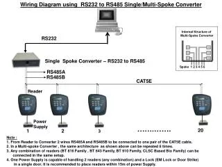
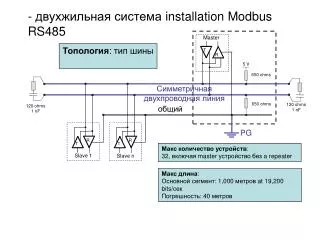
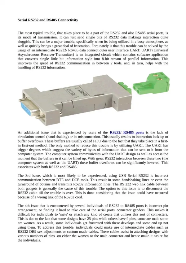
With the interface converter you can control a PTZ Dome Camera (TV7600 - TV7604) from your PC. The interface converter is connected to the PC by a serial port (RS232), and the dome camera is connected to the interface converter with a 2-core RS485 bus cable. You can operate a total of 31 dome cameras with your PC. One dome camera is connected directly to the converter and the other 30 cameras are connected to each other. The maximum transmission range from the interface converter to the last dome camera is 1200 metres.<br>For More Information visit on our website:- www.instronline.com<br>Our E-mail Address:-info@instronline.com <br>

E N D
RS485-USB User Manual ABUS TECHNOLOGIES INC. ABUS TECHNOLOGIES INC.
RS485-USB WARNING This document should be passed on to the end user. The contents of this manual are subject to change without prior notice. All rights reserved. ABUS gives no warranty of any kind with regard to this manual, including, but not limited to, fitness for a particular purpose. If any question arises or errors are found, or if any information is missing from the documents, please inform your supplier or inform at info@abustek.com. The specifications mentioned in the document are limited to those for the standard type under the specified model number break-down and do not necessarily apply for customized instruments. Please note that changes in the specifications, construction, or component parts of the instrument may not immediately be reflected in this manual at the time of change. If the customer or any third party is harmed by the use of this product, ABUS assumes no responsibility for any such harm owing to any defects in the product which were not predictable, or for any indirect damages. Although Warning hazards are related to personal injury, and Caution hazards are associated with equipment or property damage, it must be understood that operation of damaged equipment could, under certain operational conditions, result in degraded process system performance leading to personal injury or death. Therefore, comply fully with all Warning and Caution notices. Information in this manual is intended only to assist our customers in the efficient operation of our equipment. Use of this manual for any other purpose is specifically prohibited and its contents are not to be reproduced in full or part without prior approval of Technical Department, ABUS Technologies HEALTH AND SAFETY To ensure that our products are safe and without risk to health, the following points must be noted: 1. The relevant sections of these instructions must be read carefully before proceeding. 2. Warning labels on containers and packages must be observed. 3. Installation, operation, maintenance and servicing must only be carried out by suitably trained personnel and in accordance with the information given. Any deviation from these instructions will transfer the complete liability to the user. 4. Normal safety precautions must be taken to avoid the possibility of an accident occurring when operating in conditions of high pressure and/or temperature. 5. Chemicals must be stored away from heat, protected from temperature extremes and powders kept dry. Normal safe handling procedures must be used. 6. When disposing of chemicals ensure that no two chemicals are mixed. Safety advice concerning the use of the equipment described in this manual or any relevant hazard data sheets (where applicable) may be obtained from the Company address, together with servicing and spares information. 2 ABUS TECHNOLOGIES INC. ABUS TECHNOLOGIES INC.
RS485-USB . CATALOGUE Contents Page No. 1. Introduction 4 4 4 2. Presentation Technical Parameters 3. Dimensions 5 5 6 6 7 4. Connections 1. Half Duplex RS-485 (2-wire) 2. Full-Duplex RS-485 (4-wire) 3. RS-422 7 7 9 9 5. Installation 1. USB Driver Installation (Windows 98/ME/2000) 2. USB Driver Installation (Windows XP) 3. Linux and Mac 10 10 10 6. Configuration 1. Conflicts with other USB devices Windows 2. Serial Port Assignment 7. Safety Precautions 11 8. Warranty 11 3 ABUS TECHNOLOGIES INC. ABUS TECHNOLOGIES INC.
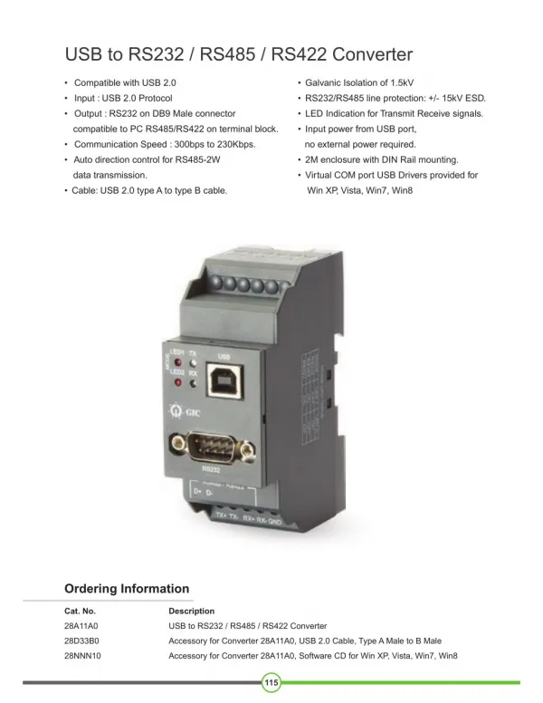
RS485-USB 1. INTRODUCTION The RS485-USB module is a cost-effective way to convert RS485 or RS422 industrial buses to a USB interface. When connected to a PC USB port the RS485- USB module is automatically detected and is installed as a native COM port, which is compatible with any existing serial communication application. Multiple modules can be installed when using USB hubs thus allowing a hassle- free configuration of a multi serial system without any IRQ or DMA configuration. 1500 Vdc isolation between the USB port and RS485/RS422 protects the PC from spikes or possible misconnections in the communication bus. 2. PRESENTATION Technical Parameters The RS485-USB converter can be configured for four-wire (Full Duplex) RS422 and RS485 or two-wire (Half Duplex) networks. When operating in two-wire RS485 the data transfer control is automatically done by the converter. Two independent and isolated RS485 networks can be supported by one RS485-USB module thus duplicating the possible number of remote devices. Computer interface: USB V1.1 Plug and Play. Operational system virtual serial port driver. Supports Windows 98/ME/XP/2000/CE, MAC & Linux 2.4.20 or superior. Field Interfaces: RS485 Half Duplex (dual buses), RS485 Full Duplex or RS422. RS485 / RS422. Jumper selected: Automatic flow control for RS485 Half Duplex. 120 Ohms internal resistors termination enabled by jumpers. Data rate: From 300 bps to 1 Mbps. Maximum RS485/RS422 cable length: Maximum number of devices in the RS485 network (unit load devices – 12 k ): 1200 m Half Duplex: 2 x 32 devices Full Duplex: 32 devices Data transmission and reception LED indicators Power: From the USB port. Consumption: <100 mA. Isolation: 1500 Vdc (1 minute) from USB interface and the RS485/RS422 interface. ±60 Vdc, 15 kV ESD. RS485/422 bus protection: USB connection: Mini-B connector. A 1.5 m cable with plugs mini-B and A is provided with the module. Screw terminal type accepting 1.5 mm² (16 AWG) wires. 0 to 50°C, 10 to 90% relative humidity, non-condensing. RS485/422 connector: Operating environment: ABS enclosure: 70 x 60 x 18 mm. 4 ABUS TECHNOLOGIES INC. ABUS TECHNOLOGIES INC.
RS485-USB 3. DIMENSIONS 4. CONNECTIONS The appropriate connection to the RS485-USB depends on the type of serial network: RS422, 2-wire RS485 or 4-wire RS485. The following figure shows a description of all RS485-USB connection terminals. A shielded twisted-pairs cable is recommended for wiring the communication bus from the converter to all network devices. The shield should be grounded and/or connected to the common terminals of all devices. The minimum recommended wire gauge is 24 AWG (0.2 mm2). Use of a wire connecting all devices common terminals is highly recommended. Damage of the networked devices may result if this recommendation is not followed. 5 ABUS TECHNOLOGIES INC. ABUS TECHNOLOGIES INC.
RS485-USB RS485 or RS422 devices from different vendors or of different models may identify the communication terminals using distinct notation. The following table shows some of this notations and its equivalence to the RS485-USB. RS485-USB CONNECTION IDENTIFICATION Rx+ ou Tx+ Rx- ou Tx- D D D1 D0 POPULAR RS485 AND RS422 CONNECTION IDENTIFICATION B A D+ D- 4.1 Half-Duplex RS485 (2-wire) To set this mode of operation, the MOD terminal (pin 4) must be left unconnected. This is the usual RS485 connection. A single twisted pair is used for data transmission and reception. Multiple RS485 devices are connected in a single bus, as shown in the next figure. Devices from different vendors may use different names for the data signal terminals. In the following figure, different identification schemes are presented for each device, with the proper connection to the RS485-USB. RS485 devices can be connected to either bus 1 or 2. The common terminal (GND – pin 5) must be connected to the corresponding terminals of all network devices, to ensure the same potential in all devices. If a common wire is not connected to all devices, all must be properly grounded according to the manufacturer recommendation. For the RS485- USB, the proper grounding terminal is pin 5 (GND). The need to install termination resistors depends on the total length of the communication bus and the communication speed (baud rate). The USB-485 has built-in termination resistors, which can be installed by wiring terminals RT1 (8) or RT2 (3) as shown in dashed lines in the last figure. For additional information in grounding, common wire and termination resistors, read the document RS485 & RS422 Basic, available on the CD provided with this product and also at www.abustek.com for download. 4.2 Full-Duplex RS485 (4-wire) To set this mode of operation, the MOD terminal (pin 4) must be connected to terminal GND (pin 5). In this mode two pairs of wires are used. Data from the RS485-USB to the networked devices 6 ABUS TECHNOLOGIES INC. ABUS TECHNOLOGIES INC.
RS485-USB are transmitted through one pair, and the other pair carries data from the devices to the RS485-USB. Multiple devices are connected as shown in the next figure. The common terminal (GND – pin 4) must be connected to the corresponding terminals of all network devices, to ensure the same potential in all devices. If a common wire is not connected to all devices, all must be properly grounded according to the manufacturer recommendation. For the RS485- USB, the proper grounding terminal is pin 5 (GND). The need to install termination resistors depends on the total length of the communication bus and the communication speed (baud rate). The RS485-USB has a built-in termination resistor, which can be installed by wiring terminal RT2 (3) as shown in dashed lines in the last figure. For additional information in grounding, common wire and termination resistors, read the document RS485 & RS422 Basics. 4.3 RS422 Full-Duplex RS485 specification supersedes RS422. The same connection instructions shown for Full-Duplex RS485 apply for RS422 connection. 5. INSTALLATION The following installation steps may be slightly different depending on your PC configuration and Windows version. Follow the Wizard instructions and use the following steps and figures to select the correct installation options. USB Driver Installation 5.1 USB Driver Installation (Windows 98 / Me / 2000) 1. Insert the RS485-USB CD in the CD-ROM drive. 2. Connect the module to a PC USB port. Windows® will detect the new hardware and after a few seconds the Add New Hardware Wizard will start. Select “Next”. 3. Select “Search for the best driver for your device (Recommended)” and select “Next”. 4. Select option “CD-ROM drive”. If the installation files are not in a CD, select option “Specify a location” and type the path for the required files. Select “Next”. 5. Select “Next” when Windows® is ready to install the driver. 6. The RS485-USB driver files will be copied to your computer and, when concluded, a window will show up informing that the wizard has finished installing the software. Select “Finish”. 7 ABUS TECHNOLOGIES INC. ABUS TECHNOLOGIES INC.
RS485-USB 7. It is possible that the previous steps repeat a second time for the completion of installation. In future connection of RS485-USB modules, it is possible that Windows® prompt again for the USB driver installation. In this case, the same wizard will be presented. Follow the above steps, but check no options in step 4, since the driver files are already in your computer. The following figures are examples of Windows 98® Add New Hardware Wizard. For Windows ME® and 2000® they look different, but the information is the same. 8 ABUS TECHNOLOGIES INC. ABUS TECHNOLOGIES INC.
RS485-USB 5.2 USB Driver Installation (Windows XP) 1. Insert the RS485-USB CD in the CD-ROM drive. 2. Connect the module to a PC USB port. Windows® will detect the new hardware and after a few seconds the new hardware wizard will start. 3. The Found New Hardware Wizard will show-up and ask if you want to connect to Windows Update to get the driver. Select the “No, not this time” and select “Next”. 4. Select “Install from a list or specific location (advanced)” and select “Next”. 5. Select “Search for the best driver in these locations” and check option “Search removable media”. Select “Next”. If the installation files are not in a CD, select option “Include this location in the search” and type the path for the required files. 6. If a warning message regarding Windows® XP compatibility appears, select “Continue Anyway”. 7. The RS485-USB driver files will be copied to your computer and, when concluded, a window will show up informing that the wizard has finished installing the software. Select “Finish”. 8. It is possible that the previous steps repeat a second time for the completion of installation. In future connection of RS485-USB modules, it is possible that Windows® prompt again for the USB driver installation. In this case, the same wizard will be presented. Follow the above steps, but select option “Install the software automatically (recommended)”, since the driver files are already installed. The following figures are examples of Windows XP® New Hardware Wizard. 5.3 Linux and Mac The USB drivers are included in Linux Kernel since version 2.4.20. No additional installation is necessary. For Mac computers, installation instructions are included in the RS485-USB CD-ROM. 9 ABUS TECHNOLOGIES INC. ABUS TECHNOLOGIES INC.
RS485-USB 6. CONFIGURATION 6.1 Conflicts with other USB devices under Windows Installation of the USB driver for the RS485-USB converter may result in conflicts with existing USB devices in the computer (mouse or other Serial/USB devices, for example). In this case, follow the procedure below to restore functionality of the affected device. Go to the Windows Control Panel and open the RS485-USB converter properties in: Control Panel / System / Hardware / Device Manager / Ports (COM & LPT) Select the desired “USB Serial Port” device, click with the right mouse button and select “Properties”. Select “Port Settings” and click on the “Advanced...” button. Uncheck the “Serial Enumerator” option. 6.2 Serial Port Assignment A few seconds after connection of the RS485-USB, Windows operating system assigns a COM port number for communication. The assigned COM port number will not change in future connections to the same USB port. Users can easily identify and modify the assigned COM port in: Control Panel / System / Hardware / Device Manager / Ports (COM & LPT) Select the desired “USB Serial Port” device, click with the right mouse button and select “Properties”. Select “Port Settings” and click on the “Advanced...” button. In “COM Port Number” list, select the serial port to be assigned. Some serial port can be marked as “in use”. Only select one of these ports if you are sure it is not being used by any other peripheral in your computer. In some cases, serial port can be marked as “in use” even when the associated device is not in the computer. In this case, it is safe to assign this port to an RS485-USB. The following figures illustrate the most important steps for this procedure. 10 ABUS TECHNOLOGIES INC. ABUS TECHNOLOGIES INC.
RS485-USB 7. SAFETY PRECAUTIONS 1. The unit should be powered for 15 minutes before use. 2. Use in ambient temperature of 0-60˚C. 3. Avoid vibrations, shock, excessive dust, corrosive chemical materials or gaseous environment. 4. Input wire should not be too long. If measured signal have to be far away from the unit, please use 2-core shielded cable. 5. Use this instrument in the scope of its specifications, otherwise fire or malfunctions may result. 6. Contact of the instrument, with organic solvents or oils should be avoided. 7. Do not turn on the power supply until all of the wiring is completed. Otherwise electrical shock, fire or malfunction may result. 8. Do not disassemble, repair or modify the instrument. 9. All connections should be tightened properly. 10. Power supply should be constant, should not be fluctuating. 8. WARRANTY ABUS provides the original purchaser of this instrument a one (1) year warranty against defects in material and workmanship under the following terms: The one year warranty begins on the day of shipment as stated on the sales bill. During the warranty period all costs of material and labor will be free of charge provided that the instrument does not show any evidence of misuse. For maintenance, return the instrument with a copy of the sales bill to our factory. All transportation and insurance costs should be covered by the owner of the equipment. Should any sign of electrical or mechanical shock, abuse, bad handling or misuse be evident the warranty voids and maintenance costs will be charged. ABUS TECHNOLOGIES INC. ABUS TECHNOLOGIES INC. www.abustek.com, E-Mail: info@abustek.com 11 ABUS TECHNOLOGIES INC. ABUS TECHNOLOGIES INC.