Download
1 / 5
50 likes | 59 Vues
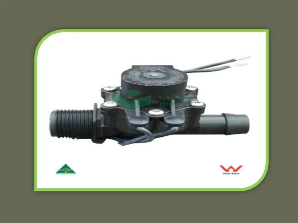
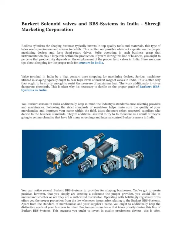
"PICOSOL precision miniature solenoid valves combine small size and low power with high flow, high repeatability and long life. They are well suited to be customized to OEM specifications. PICOSOL platform includes on/off and media separated valves.<br><br>2/2, 3/2 and NC/NO/UNI<br>High flow to size ratio<br>Best repeatability"<br>For More Information visit on our website:- www.instronline.com<br>Our E-mail Address:-info@instronline.com <br>

E N D
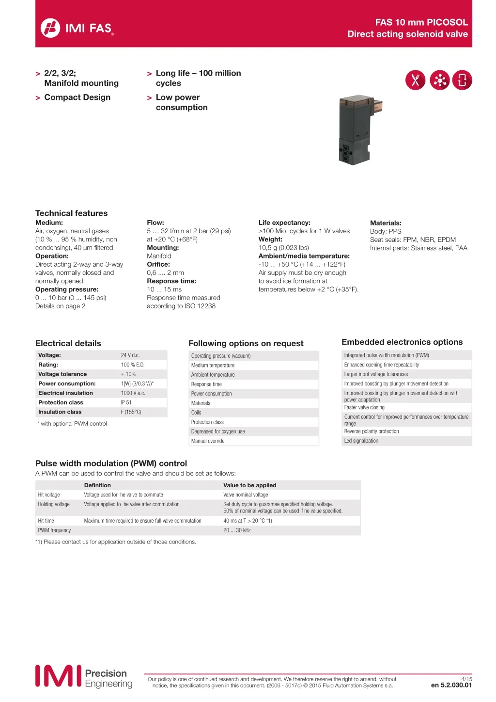
FAS 10 mm PICOSOL Direct acting solenoid valve > 2/2, 3/2; Manifold mounting > Compact Design > Long life – 100 million cycles > Low power consumption Technical features Medium: Air, oxygen, neutral gases (10 % ... 95 % humidity, non condensing), 40 μm filtered Operation: Direct acting 2-way and 3-way valves, normally closed and normally opened Operating pressure: 0 ... 10 bar (0 ... 145 psi) Details on page 2 Flow: 5 … 32 l/min at 2 bar (29 psi) at +20 °C (+68°F) Mounting: Manifold Orifice: 0,6 .... 2 mm Response time: 10 ... 15 ms Response time measured according to ISO 12238 Life expectancy: ≥100 Mio. cycles for 1 W valves Weight: 10,5 g (0.023 lbs) Ambient/media temperature: -10 ... +50 °C (+14 ... +122°F) Air supply must be dry enough to avoid ice formation at temperatures below +2 °C (+35°F). Materials: Body: PPS Seat seals: FPM, NBR, EPDM Internal parts: Stainless steel, PAA Embedded electronics options Electrical details Following options on request Voltage: Rating: Voltage tolerance Power consumption: Electrical insulation Protection class Insulation class 24 V d.c. 100 % E.D. ± 10% 1[W] (3/0,3 W)* 1000 V a.c. IP 51 F (155°C) Integrated pulse width modulation (PWM) Enhanced opening time repeatability Larger input voltage tolerances Improved boosting by plunger movement detection Improved boosting by plunger movement detection wi h power adaptation Faster valve closing Current control for improved performances over temperature range Reverse polarity protection Led signalization Operating pressure (vacuum) Medium temperature Ambient temperature Response time Power consumption Materials Coils Protection class Degreased for oxygen use Manual override * with optional PWM control Pulse width modulation (PWM) control A PWM can be used to control the valve and should be set as follows: Definition Voltage used for he valve to commute Voltage applied to he valve after commutation Value to be applied Valve nominal voltage Set duty cycle to guarantee specified holding voltage. 50% of nominal voltage can be used if no value specified. Hit voltage Holding voltage Hit time PWM frequency Maximum time required to ensure full valve commutation 40 ms at T > 20 °C *1) 20 ... 30 kHz *1) Please contact us for application outside of those conditions. Our policy is one of continued research and development. We therefore reserve the right to amend, without notice, the specifications given in this document. (2006 - 5017d) © 2015 Fluid Automation Systems s.a. 4/15 en 5.2.030.01
FAS 10 mm PICOSOL Direct acting solenoid valve Technical data - standard models Symbol Operation Orifice Operating pres- sure (bar) (psi) kv*1) (l/min) Power consumption (W) *2) Voltage Manual override *3) Seal mate- rial Drawing Model (mm) (V d.c.) no. 0,6 1,1 0 ... 10 0 ... 4 0 ... 145 0 ... 58 0,12 0,3 1 1 24 24 With With FPM FPM 2 2 11-221PI060H1+1111+AYV 11-221PI011H1+1111+AYR 2 0 3 12 10 2/2 NO (3/2 mounting pattern) 2 0,6 0,8 1,1 0,8 1,2 1,6 0,6 0,8 1,1 1,3 0,8 0 ... 8 2 ... 8 0,5 ... 2,1 0 ... 8 0 ... 4 0 ... 8 0 ... 8 2 ... 8 2 ... 8 2 ... 6,5 0 ... 6 0 ... 116 29 ... 116 7.2 ... 30 0 ... 116 0 ... 58 0 ... 116 0 ... 116 29 ... 116 29 ... 116 29 ... 94 0 ... 87 0,12 0,19 0,3 0,2 0,39 0,54 0,12 0,19 0,37 0,44 0,19 1 1 1 1 1 4/0,4 1 1 3/0,3 3/0,3 1 24 24 24 24 24 24 24 24 24 24 24 With With With Without Without Without With With With With With FPM FPM FPM FPM FPM FPM FPM FPM FPM FPM FPM 2 2 2 1 1 1 2 2 2 2 2 11-211PI060H1+1111+AYV 11-211PI01-H1+1111+AYV 11-211PI011H1+1111+AYV 11-211P601-H1+1311+AYV 11-211P602-H1+1311+AYR 11-211P603-H1+6311+AXA 11-311PI060H1+1111+AYV 11-311PI01-H1+1111+AYV 11-311PI011H1+6111+AZR 11-311PI013H1+6111+AZR 11-321PI01-H1+1111+AYV 2 12 10 2/2 NC (3/2 mounting pattern) 1 2 12 10 2/2 NC 1 2 12 10 3/2 NC 1 3 3 2 10 12 3/2 NO 1 3 1 3 3 0,8 0 ... 2 0 ... 29 0,18 1 24 With FPM 2 11-331PI01-H1+1111+AYV 2 12 10 3/2 UNI 1 3 3 *1) Cv = 0,07 kv *2) Power consumption: “boosting power during ca. 50 ms”/ “holding power” *3) Push only Accessories Electrical connection Mounting plate with barbed fittings for 3 mm ØID tubing (up to 2 bar) Mounting manifold with M3 threads — 1 position Mounting manifold with M5 threads — 1 ... 8 positions Electrical connector Molex 50-57- 9402 with 300 mm flying leads Page 4 Page 4 Page 5 Page 5 S111.1772 S110.1277 Available on request S110.1032 Our policy is one of continued research and development. We therefore reserve the right to amend, without notice, the specifications given in this document. (2006 - 5017d) © 2015 Fluid Automation Systems s.a. en 5.2.030.02 4/15
FAS 10 mm PICOSOL Direct acting solenoid valve Dimensions 1 Dimensions shown in mm Projection/First angle 6,4 2,54 2 18,5 32 23 A 7 3 6,2 12,4 4 2,6 A 10 1 3,5 22,7 1,9 M2 3,9 8,5 2 4,5 2 2 6,4 2,54 2 18,5 32 23 A 6,2 3 6,8 12,4 4 A 10 M1,6 0,2 3,5 22,7 3 2 1 2,7 2,7 1,6 0,8 2,4 2 4 1 Manual override, push only 2 Sealing area 3 The recommended mounting screw tightening torque is 0,15 Nm. 4 Connector mates with Molex 50-57-9402 All solenoids are supplied with mounting screws and gasket. Our policy is one of continued research and development. We therefore reserve the right to amend, without notice, the specifications given in this document. (2006 - 5017d) © 2015 Fluid Automation Systems s.a. en 5.2.030.03 4/15
FAS 10 mm PICOSOL Direct acting solenoid valve Mounting plate with barbed fittings for 3 mm ØID tubing (up to 2 bar) Model: S111.1772 Mounting manifold Model: S110.1277 Dimensions shown in mm Projection/First angle 14,5 1 A 2 3 6,5 15 10,5 2 2,6 2 9 7 1 R3 6,5 M5 5 10,5 3 5,5 7,5 19,5 5,5 10 A M5 20 12 5,5 M5 5 ø1,8 ø3,6 13 1 Mounting thread M2 x 5 deep Mounting manifold Model: on request M5 M5 20 14 4,5 5 6 10,5 ±0,1 8 (N-1) x 10,5 5 3 15 3 X Y M5 10,5 6 10,5 ±0,1 5 Mounting thread M3 x 4,5 deep (N-1) x 10,5 Valve station X 2 3 4 5 6 7 8 Y 22,5 33 43,5 54 64,5 75 85,5 16,5 27 37,5 48 58,5 69 79,5 Our policy is one of continued research and development. We therefore reserve the right to amend, without notice, the specifications given in this document. (2006 - 5017d) © 2015 Fluid Automation Systems s.a. en 5.2.030.04 4/15
FAS 10 mm PICOSOL Direct acting solenoid valve Electrical connector Model: S110.1032 Dimensions shown in mm Projection/First angle 5,5 15 2,54 5 Warning These products are intended for use in air, oxygen and neutral gas systems only. Do not use these products where pressures and temperatures can exceed those listed under »Technical features«. The system designer is warned to consider the failure modes of all component parts used in fluid power systems and to provide adequate safeguards to prevent personal injury or damage to equipment in the event of such failure. System designers must provide a warning to end users in the system instructional manual if protection against a failure mode cannot be adequately provided. Before using these products with fluids other than those specified, for non-industrial applications, life-support systems, or other applications not within published specifications, consult IMI FAS. Through misuse, age, or malfunction, components used in fluid power systems can fail in various modes. Our policy is one of continued research and development. We therefore reserve the right to amend, without notice, the specifications given in this document. (2006 - 5017d) © 2015 Fluid Automation Systems s.a. en 5.2.030.05 4/15