Download
1 / 10
130 likes | 240 Vues
"ITEM: VP2310BD461MB201<br>1). All-digital control electronics<br>2). Variable pressure control, external pressure control upon request<br>3). Optional: serial interfacing with VP-Tool program<br>4). Optional actuation via fieldbus<br>5). Valve conforms to CE<br>6). Free of lacquer affecting substances<br>"<br>For More Information visit on our website:- www.instronline.com<br>Our E-mail Address:-info@instronline.com <br>

E N D
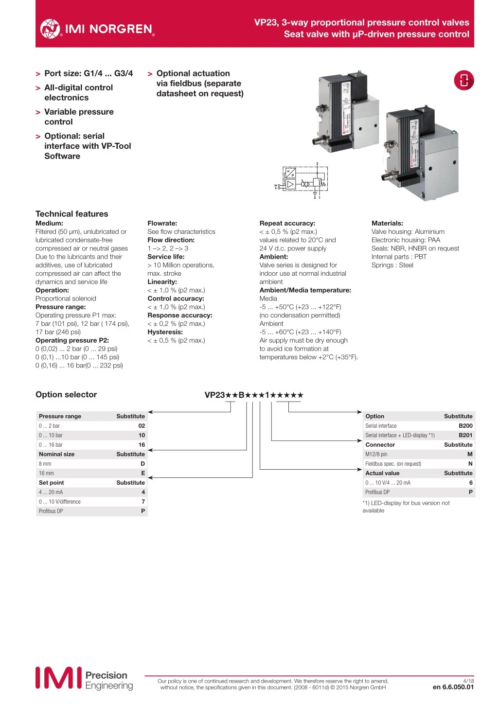
VP23, 3-way proportional pressure control valves Seat valve with μP-driven pressure control > Port size: G1/4 ... G3/4 > All-digital control electronics > Variable pressure control > Optional: serial interface with VP-Tool Software > Optional actuation via fieldbus (separate datasheet on request) 2 p w x 3 1 Technical features Medium: Filtered (50 μm), unlubricated or lubricated condensate-free compressed air or neutral gases Due to the lubricants and their additives, use of lubricated compressed air can affect the dynamics and service life Operation: Proportional solenoid Pressure range: Operating pressure P1 max: 7 bar (101 psi), 12 bar ( 174 psi), 17 bar (246 psi) Operating pressure P2: 0 (0,02) ... 2 bar (0 ... 29 psi) 0 (0,1) ...10 bar (0 ... 145 psi) 0 (0,16) ... 16 bar(0 ... 232 psi) Flowrate: See flow characteristics Flow direction: 1 –> 2, 2 –> 3 Service life: > 10 Million operations, max. stroke Linearity: < ± 1,0 % (p2 max.) Control accuracy: < ± 1,0 % (p2 max.) Response accuracy: < ± 0,2 % (p2 max.) Hysteresis: < ± 0,5 % (p2 max.) Repeat accuracy: < ± 0,5 % (p2 max.) values related to 20°C and 24 V d.c. power supply Ambient: Valve series is designed for indoor use at normal industrial ambient Ambient/Media temperature: Media -5 ... +50°C (+23 ... +122°F) (no condensation permitted) Ambient -5 ... +60°C (+23 ... +140°F) Air supply must be dry enough to avoid ice formation at temperatures below +2°C (+35°F). Materials: Valve housing: Aluminium Electronic housing: PAA Seals: NBR, HNBR on request Internal parts : PBT Springs : Steel Option selector VP23˙˙B˙˙˙1˙˙˙˙˙ Pressure range 0 ... 2 bar 0 ... 10 bar 0 ... 16 bar Nominal size 8 mm 16 mm Set point 4 ... 20 mA 0 ... 10 V/difference Profibus DP Substitute Option Serial interface Serial interface + LED-display *1) Connector M12/8 pin Fieldbus spec. (on request) Actual value 0 ... 10 V/4 ... 20 mA Profibus DP Substitute 02 10 16 B200 B201 Substitute Substitute M N D E Substitute Substitute 6 P 4 7 P *1) LED-display for bus version not available Our policy is one of continued research and development. We therefore reserve the right to amend, without notice, the specifications given in this document. (2008 - 6011d) © 2015 Norgren GmbH 4/18 en 6.6.050.01
VP23, 3-way proportional pressure control valves Seat valve with μP-driven pressure control Function The electronic pressure controller is used in conjunction with an electric set-point (control signal) to quickly and precisely set a pressure at the pressure connection (2). Even with consumption of the medium (compressed air or neutral gases) the output pressure is controlled (see flow rate characteristics) Proportional valves are used in many different applications across all sectors of industry. They are used anywhere where precise and fast direct or indirect control of pressure, force, rotational speed etc. is required. Application example: Contact pressure control of welding electrodes in automotive manufacture Operating principle The valve has a closed loop controller, meaning that the output pressure is constantly being measured by the internal pressure sensor and compared to the specified set-point. If the output pressure is lower than the set pressure or if a higher pressure is desired, the pneumatic control plunger is actuated by the electric proportional solenoid. A connection is then established between connection 1 (input pressure) and 2 (output pressure) until the pressure is the same as the specified set-point. If the output pressure is higher than the set pressure or if a lower pressure is desired, the pneumatic control plunger is actuated by the electric proportional solenoid. A connection is then established between connection 1 (input pressure) and 3 (ventilation connection) until the pressure is the same as the specified set-point. In addition, after the supply voltage is switched off, the output pressure set last is vented down to 0 bar. Assembly The electronic pressure controller consists of: - Proportional solenoid - An integrated pressure sensor - µP-driven control electronics - Serial interface - A pneumatic control plunger - Optional: Fieldbus interface Configuration software VP-Tool (please order separately) LED display for the size of the output pressure Electrical parameters Endurance limit in relation to oscillations to DIN EN 60068-2-6: 10g at 12-500Hz in switched-off-status Durability under shock effect to DIN EN 68-2-67: 30 g/10 shocks Valves should not be used in safety systems that require blocking or exhaust valves Without power the pneumatic connection 2 -> 3 is open Supply Supply voltage UB 18 ... 32 V d.c. Residual ripple max. [%] Current consump- tion at 16 bar 10 approx. 1,8 A at 24 V d.c. NG 8,16 max. [A] NG 8,16 static at 25°C (corrected) [A] approx. 1,4 A at 24 V d.c. NG 8,16 max. [A] NG 8,16 static at 25°C (corrected) [A] approx. 1,2 A at 24 V d.c. NG 8,16 max. [A] NG 8,16 static at 25°C (corrected) [A] approx. 1,2 A at 24 V d.c. Current consump- tion at 10 bar approx. 1,8 A at 24 V d.c. Current consump- tion at 2 bar approx. 1,8 A at 24 V d.c. Inputs (signal) Set point W (+/-U d) analogue differential Voltage signal UE (V) Output pressure actual value X(I) 0 ... 10 Current signal of pneumatic output pressure IA (mA) Load resistance RL (Ω) 0 (4) ... 20 mA = 0 ... max. p2 500 recommended Input resistance RI (kΩ) Set point W(I) analogue: Current signal UE (mA) Burden (Ω) Max. input voltage (V) 170 4 ... 20 500 -10 ... 40 Outputs (signal) Output pressure actual value X(U) Voltage signal of pneumatic output pressure UA (V) Output »pressure reached« X (comp) 0 ... 10 V = 0 ... max. p2 Switching range (% max. p2) Digital output signal Control pressure outside of switching range (X≠W) Pressure reached (X = W) (V) Outout current max. (mA) +/-2% PLC-Level Low Output current max. IA (mA) 1 High 10 Our policy is one of continued research and development. We therefore reserve the right to amend, without notice, the specifications given in this document. (2008 - 6011d) © 2015 Norgren GmbH en 6.6.050.02 4/18
VP23, 3-way proportional pressure control valves Seat valve with μP-driven pressure control Pneumatic parameters Recommended application area by nominal value: NG8: Volume (closed) from 100 ... 1500 cm3 NG16: Volume (closed) from 1000 ... 8000 cm3 Residual ripple max. Input pressure p1 max. Output pressure p2 max. [%] [bar] [bar] 10 17/12/7 0-16 / 0-10 / 0-2 Flow quantity NG 8 Flow quantity NG16 Switching times (10%-90%) nominal size 8 at volume 400 cm3 Typical values for P1=12 bar Pressure build-up (tr) 1 bar ... 9 bar Pressure build-up (tf) 4 bar ... 5 bar Pressure drop (tr) 9 bar ... 1 bar Pressure drop (tf) 5 bar ... 4 bar Switching times (10%-90%), nominal size 16 at volume 1000 cm3 Typical values for P1=12 bar Pressure build-up (tr) 1 bar ... 9 bar Pressure build-up (tf) 4 bar ... 5 bar Pressure drop (tr) 9 bar ... 1 bar Pressure drop (tf) 5 bar ... 4 bar [l/min] [l/min] see diagram see diagram 100 [ms] 50 [ms] 250 [ms] 50 [ms] 100 [ms] 50 [ms] 100 [ms] 50 [ms] Test assembly flow CETOP RP 84 P.: flow characteristic of pneumatic devices Step-response diagram p (bar) 10 8 6 4 2 tr tf t (ms) 0 0 200 400 600 800 1000 Our policy is one of continued research and development. We therefore reserve the right to amend, without notice, the specifications given in this document. (2008 - 6011d) © 2015 Norgren GmbH en 6.6.050.03 4/18
VP23, 3-way proportional pressure control valves Seat valve with μP-driven pressure control Pneumatic characteristics curves Flow rate characteristic as a function of the set-point (voltage/current) and input pressure 7 bar, 12 bar, 17 bar for nominal value 8 and 16 Static characteristics "Z" p2 p2 = f(w) (bar) p2 (bar) 16 10 2,0 1,8 1,6 1,4 1,2 1,0 0,8 0,6 0,4 0,2 9 8 7 6 5 4 3 2 1 0 14 16 10 2,0 p2 = f(w) 12 10 8 6 4 2 0,16 0,10 0,02 0 0 0 0 0 0 1 2 3 4 5 6 7 8 9 10 W [%] 0 1 2 3 4 5 6 7 8 t (ms) 9 10 UE[V] Z 4 5,6 7,2 8,8 10,4 12 13,6 15,2 16,8 18,4 20 I E [mA] Flow rate characteristics NG 8/P1=7 bar, 12 bar, 17 bar p (bar) p (bar) p (bar) 16 6 14 5 10 12 4 10 8 8 6 6 2 4 4 1 2 2 0 0 0 250 500 750 1000 1250 1500 1750 2000 500 1000 1500 2000 2500 3000 3500 500 1000 1500 2000 2500 3000 3500 4000 Q (l/min) Q (l/min) Q (l/min) Flow rate characteristics NG 16/connection plat ae 1/2” (NG12); P1=7 bar, 12 bar, 17 bar p (bar) p (bar) p (bar) 16 6 14 5 10 12 4 10 8 8 6 6 2 4 4 1 2 2 0 0 0 0 1000 2000 3000 4000 5000 6000 7000 8000 0 2000 4000 6000 8000 10000 12000 Q (l/min) 0 2000 4000 6000 8000 10000 12000 14000 16000 Q (l/min) Q (l/min) Flow rate characteristics NG 16/connection plate 3/4“ (NG20); P1=7 bar, 12 bar, 17 bar p (bar) p (bar) p (bar) 16 6 14 5 10 12 4 8 10 8 6 6 4 2 4 2 1 2 0 0 0 0 2500 5000 7500 10000 12500 15000 17500 0 2000 4000 6000 800010000 Q (l/min) 0 4000 8000 12000 16000 20000 1000 3000 5000 7000 2000 6000 10000 14000 18000 Q (l/min) Q (l/min) Our policy is one of continued research and development. We therefore reserve the right to amend, without notice, the specifications given in this document. (2008 - 6011d) © 2015 Norgren GmbH en 6.6.050.04 4/18
VP23, 3-way proportional pressure control valves Seat valve with μP-driven pressure control Functional descriptions, status LED and amplification degree setting General Status LED indicator) Status Status-LED Device off off Device running single-colour green Valve fault* red* Outout current max. (mA) 10 Function Option LED indicator Pressure range 0 ... 2 bar 0 ... 10 bar 0 ... 16 bar Display values 0,00 ... 2,00 00,0 ... 10,0 00,0 ... 16,0 2 coloured LED-display LED indicator green LED indicator red * Potential error sources: - Current supply or internal references outside the permitted range - Valve not adjustable (X≠W Time out) - Program cycle interrupted pressure devation from setpoint < +/- 2% pressure devation from setpoint > +/- 2% Setting controller gain via PC with VP-Tool The gain of the integrated controller is set in the factory to a value which allows universal use of the valve. If necessary, the controller gain can be varied to suit a specific pneumatic application of the valve. When the screw plug is opened the interface connector can connected and via VP-Tool the controller gain can be adjusted. Adjustment by VP-Tool via serial interface Connection diagrams 1. Standard connection (M12x1; 8-pin) Status 3 4 2 5 7 6 1 1 W (I), white 2 X (komp), brown 3 W (-Ud), green 4 W (+Ud), yellow 5 X (I), grey 6 Ub pink 7 GND blue 8 X (U), red 1 2 3 4 5 6 7 8 5 6 4 7 5 6 4 7 3 8 1 3 2 1 2 1 2 3 4 5 6 7 8 Assignment Supply: Pin Description Colour of connection cable 6 7 Ub GND power supply 18 ... 32 V d.c. power ground/PGND Pink Blue Input Set point: Pin Output Pin Description Colour of connection cable Description Colour of connection cable 3 4 1 -W +W W(I) Analogue GND/set point input voltage 0 ... 10 V Green Signal/set point input voltage 0 ... 10V Set point input current 4 ... 20 mA 5 8 X(I) X(U) Actual value current 4 ... 20 mA Actual value voltage 0 ... 10V Grey Red Yellow White Voltage output refers to Gnd Pin 7. Due to the voltage drop on the ground wire you should consider an accuracy loss of the voltage output. Both outputs are active as standard. Depending on the order number, both outputs (U/I) but only the ordered input will be active. Voltage input 0 ... 10 V between pins 4 and 3 Current input between pins 1 and 7 Comparator output/pressure switch* Pressure reached: Pin Description 3. Serial interface connection Colour of connection cable 2 X (comp) Digital output signal PLC level (I max) =3,3 mA High : pressure reached devation Iw-xI < ± 2% Low: pressure not reached devation Iw-xI > ± 2% Brown Connection of serial interface Remove fitting, plug in the interface cable, establish communication with VP-Tool. The output relates to Gnd Pin 7 * selectable via VP-Tool Our policy is one of continued research and development. We therefore reserve the right to amend, without notice, the specifications given in this document. (2008 - 6011d) © 2015 Norgren GmbH en 6.6.050.05 4/18
VP23, 3-way proportional pressure control valves Seat valve with μP-driven pressure control Connecting plugs Description Specification Model Connecting plug M12x1; 8-pin; 5 m, 8 x 0,25 mm2, straight 0250811 Connecting plug M12x1; 8-pin; 5 m, 8 x 0,25 mm2, 90° 0250813 Connecting plug M12x1; 8-pin; convertible, 90° 0252383 Connector (Bus only) M12x1, 5-pin, 5 m, 90°, A-Coded, open (power) 0252088 Connector (Bus only) M12x1, 5-pin, 5 m, 90°, B-Coded, open (Bus in) 0251310 Connector (Bus only) M12x1, 5-pin, 5 m, 90°, B-Coded, open (Bus out) 0251312 Connector with cable (Bus only) Plug M12x1, 5-pin, 5m, 90°, B-Coded, (Bus in/out) 0252091 Note: Cable material PUR shielded Connection plates Serial interface accessories Adaptor cable Description Description Ports Model Model Connection plate NG 8 G1/4 0542636 Adaptor cable with software CD VP tool 5988319 Connection plate NG 8 G3/8 0543705 Connection plate NG16 G1/2 0542814 Connection plate NG16 G3/4 0542840 Our policy is one of continued research and development. We therefore reserve the right to amend, without notice, the specifications given in this document. (2008 - 6011d) © 2015 Norgren GmbH en 6.6.050.06 4/18
VP23, 3-way proportional pressure control valves Seat valve with μP-driven pressure control Basic dimensions Standard ND8 Dimensions in mm Projection/First angle 82 4 10,5 37 M5 55 44 5,5 35,5 18,5 Ø5,5 18,5 5,5 Ø10 27,5 M12 x 1 44,5 ø 10 ø 5,5 ~126 ~108 ~103 91 7,5 25 50 30 4 10 7,5 2 1 3 1 35,5 2 Connection plate 55 6,5 ~130 71 15 13,5 6,5 17,5 1 6 7 5 2 4 3 ND8 with serial interface, LED indicator 25 2 1 3 1 6 Status 7 5 2 4 3 Our policy is one of continued research and development. We therefore reserve the right to amend, without notice, the specifications given in this document. (2008 - 6011d) © 2015 Norgren GmbH en 6.6.050.07 4/18
VP23, 3-way proportional pressure control valves Seat valve with μP-driven pressure control Dimensions ND16 Dimensions in mm Projection/First angle 23 23 M5 3 2 25 52 1 70 52 14,5 Ø6,6 17,5 5,5 4 4 Ø11 48 M12 x 1 73 ø 11 ø 6,6 ~146 ~128 11 ~123 111 25 70 50 47 4 20 2 1 3 8,5 59 1 97 2 Connection plate 7,5 ~160 30 71 22 15 13,5 17,5 14 1 57 6 7 5 2 4 3 10,5 38 Dimensions optional serial interface, LED indicator ND16 2 1 3 1 6 Status 7 5 2 4 3 Our policy is one of continued research and development. We therefore reserve the right to amend, without notice, the specifications given in this document. (2008 - 6011d) © 2015 Norgren GmbH en 6.6.050.08 4/18
VP23, 3-way proportional pressure control valves Seat valve with μP-driven pressure control Connection plate 0543705, G3/8 ports preferable for VP23xxBDxx1xxxxx valve Dimensions in mm Projection/First angle A - A 0542636, G1/4 ports optional for VP23xxBDxx1xxxxx valve 44,5 A - A 7,5 10 8-10 6.5 5,5 A 18,5 13 G 1/4 35,5 2 2 3 3 19 31 M5 48,5 55 44 44 1 1 Ø 10 A 5,5 Ø 5,5 2,5 6,5 20 10,5 28,5 27,5 37 36,5 55 0542840, G3/4 ports preferable for VP23xxBExx1xxxxx valve A - A Our policy is one of continued research and development. We therefore reserve the right to amend, without notice, the specifications given in this document. (2008 - 6011d) © 2015 Norgren GmbH en 6.6.050.09 4/18
VP23, 3-way proportional pressure control valves Seat valve with μP-driven pressure control Connection plate 0542814, G1/2 ports optional for VP23xxBExx1xxxxx valve Dimensions in mm Projection/First angle A - A Warning These products are intended for use in industrial compressed air systems only. Do not use these products where pressures and temperatures can exceed those listed under »Technical features/data«. Before using these products with fluids other than those specified, for non-industrial applications, life-support systems or other applications not within published specifications, consult IMI Precision Engineering, Norgren GmbH. Through misuse, age, or malfunction, components used in fluid power systems can fail in various modes. The system designer is warned to consider the failure modes of all component parts used in fluid power systems and to provide adequate safeguards to prevent personal injury or damage to equipment in the event of such failure. System designers must provide a warning to end users in the system instructional manual if protection against a failure mode cannot be adequately provided. System designers and end users are cautioned to review specific warnings found in instruction sheets packed and shipped with these products. Our policy is one of continued research and development. We therefore reserve the right to amend, without notice, the specifications given in this document. (2008 - 6011d) © 2015 Norgren GmbH en 6.6.050.10 4/18