Download
1 / 80
820 likes | 960 Vues
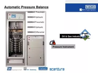
Pressure balances (dead-weight testers) are the most accurate instruments available on the market for the calibration of electronic or mechanical pressure measuring instruments. The direct measurement of the pressure (p = F/A), as well as the use of high-quality materials enable a very small measurement uncertainty, in conjunction with an excellent long-term stability. The pressure balance (dead-weight tester) has therefore been used for years in factory and calibration laboratories in industry, national institutes and research laboratories.<br><br>For More Information visit on our website:- www.instronline.com<br>Our E-mail Address:-info@instronline.com <br>

E N D
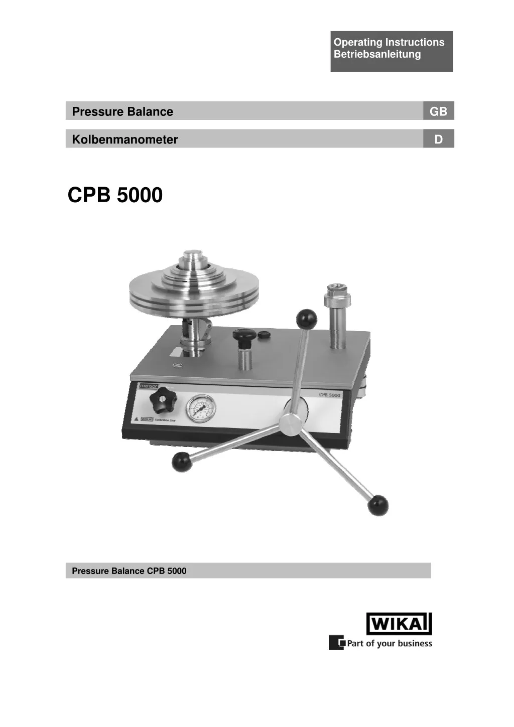
Operating Instructions Betriebsanleitung Pressure Balance GB Kolbenmanometer D CPB 5000 Pressure Balance CPB 5000
Pressure Balance CPB 5000 GB GB Operating Instructions Pressure Balance Page 4 - 39 D Betriebsanleitung Kolbenmanometer Seite 40 - 77 Information This symbol provides you with information, notes and tips. Warning! This symbol warns you against actions that can cause injury to people or damage to the instrument. 2 WIKA Operating Instructions Pressure Balance Version 3.1
Pressure Balance CPB 5000 C C Co o on n nt t te e en n nt t ts s s GB 1. General . ................................................................................................... 5 1.1 General Instructions . ................................................................................................................... 5 1.2 Safety Instructions . ..................................................................................................................... 6 2. Product Description . ................................................................................................... 7 2.1 General Product Information . ..................................................................................................... 7 2.2 Basic principle of the Pressure Balance . .................................................................................. 8 2.3 Factors at work 2.3.1 Local fluctuations in the gravity-value 2.3.2 Temperature (Piston/Cylinder) 2.3.3 Ambient conditions 2.3.4 How the cross-sectional surface responds to pressure . ........................................................................................................................... 8 . .................................................................................. 8 . ............................................................................................... 9 . ................................................................................................................. 9 . ................................................... 10 2.4 Arrangement of control elements . ........................................................................................... 10 2.4.1 Pneumatic low-pressure base . .............................................................................................. 11 2.4.2 Pneumatic high-pressure / vacuum base . ........................................................................... 12 2.4.3 Hydraulic base . ....................................................................................................................... 13 3. Commissioning and Operation . ................................................................................................. 14 3.1 Preparation 3.1.1 Setting up the Device 3.1.1.1 Instructions for pneumatic high-pressure / vacuum version 3.1.1.2 Instructions for pneumatic version with integrated gas to oil separator 3.1.1.3 Instructions for hydraulic version 3.1.2 Installing the ConTect System 3.1.2.1 Connection for piston/cylinder system with M30 x 2 female thread 3.1.2.2 Connection for piston/cylinder system with ConTect quick connector 3.1.2.3 Vacuum piston/cylinder system 3.1.2.4 Connection for piston/cylinder system with integrated separator, M30 x 2 female thread ....... .19 3.1.3 Connecting the test specimen . ............................................................................................. 20 3.1.4 Venting the System (Hydraulic Design only) . ................................................................................................................................ 14 . ............................................................................................................ 14 . ........................................ 14 . ..................... 14 . .................................................................................... 15 . ............................................................................................. 16 . ............................. 16 . ....................... 17 . ....................................................................................... 18 . ...................................................................... 20 3.2 Operation 3.2.1 Weight Pieces 3.2.2.1 Approaching the pressure value – hydraulic base 3.2.2.2 Approaching the pressure value – pneumatic low-pressure base 3.2.2.3 Approaching the pressure value – pneumatic high-pressure / vacuum base 3.2.2.4 Approaching the pressure value – pneumatic version with separator 3.2.3 Pressure stable . ...................................................................................................................... 23 3.2.4 Next pressure level . ................................................................................................................ 24 . ................................................................................................................................. 21 . ........................................................................................................................ 21 . ......................................................... 22 . ............................... 22 . ............. 23 . ......................... 23 3.2.5 Vacuum operation . ................................................................................................................. 24 3.2.5.1 Weight pieces for vacuum . ................................................................................................. 24 3.2.5.2 Approaching the vacuum values . ...................................................................................... 25 3.2.5.3 Vacuum stable . .................................................................................................................... 25 3.2.5.4 Next vacuum level 3.2.6 Releasing pressure – hydraulic , pneumatic and vacuum . .............................................................................................................. 25 . ................................................ 25 3.3 Disassembly . .............................................................................................................................. 26 4. Troubleshooting measures . ................................................................................................. 27 5. Maintenance and Care . ................................................................................................. 28 3 WIKA Operating Instructions Pressure Balance Version 3.1
Pressure Balance CPB 5000 5.1 Cleaning 5.1.1 Piston/Cylinder system 5.1.1.1 Hydraulic piston/cylinder system 5.1.1.2 Pneumatic piston/cylinder system 5.1.2 Weight Set . .............................................................................................................................. 31 GB . .................................................................................................................................... 28 . ......................................................................................................... 28 . ..................................................................................... 28 . ................................................................................... 30 5.2 Wear Parts . ................................................................................................................................. 31 5.3 Changing the Hydraulic Oil (Hydraulic Design only) 5.3.1 Removing Hydraulic Oil 5.3.2 Filling in of Hydraulic Oil 5.3.3 Venting of the System (after Complete Filling only) . ............................................................ 32 . ........................................................................................................ 32 . ...................................................................................................... 32 . .......................................................... 32 5.4 Recalibration . ............................................................................................................................. 33 6. Specifications . ................................................................................................. 34 7. Tables of masses . ................................................................................................. 37 7.1 Hydraulic models . ...................................................................................................................... 37 7.2 Pneumatic models . .................................................................................................................... 38 8. Accessories . ................................................................................................. 39 4 WIKA Operating Instructions Pressure Balance Version 3.1
Pressure Balance CPB 5000 GB 1. General . 1.1 General Instructions . In the following chapters detailed information on the CPB 5000 pressure balance and its proper use can be found. Should you require further information, or should there be problems which are not dealt within detail in the operating instructions, please contact the address below: WIKA Alexander Wiegand SE & Co. KG Alexander Wiegand Strasse D-63911 Klingenberg Tel: +49-(0)9372/132-0 Fax: +49-(0)9372/132-406 E-Mail: calibration@wika.de If nothing to the contrary is agreed, the pressure balance is calibrated in compliance with the currently valid body of international regulations and can be referred directly to a national standard. The warranty period for the pressure balance is 24 months according to the general terms of supply of ZVEI. The guarantee is void if the appliance is put to improper use or if the operating instructions are not observed or if an attempt is made to open the appliance or to release attachment parts or the tubing. We also point out that the content of these operating instructions neither forms part of an earlier or existing agreement, assurance or legal relationship nor is meant to change these. All obligations of WIKA Alexander Wiegand SE & Co. KG result from the respective sales contract and the general business terms of WIKA Alexander Wiegand SE & Co. KG. WIKA is a registered trade mark of WIKA Alexander Wiegand SE & Co. KG. Names of companies or products mentioned in this handbook are registered trade marks of the manufacturer. The devices described in this manual represent the latest state of the art in terms of their design, dimension and materials. We reserve the right to make changes to or replace materials without any obligation to give immediate notification. Duplication of this manual in whole or in part is prohibited. © 2010 Copyright WIKA Alexander Wiegand SE & Co. KG. All rights reserved. 5 WIKA Operating Instructions Pressure Balance Version 3.1
Pressure Balance CPB 5000 1.2 Safety Instructions GB . Read these operating instructions carefully prior to operating the pressure balance CPB 5000. Its trouble-free operation and reliability cannot be guaranteed unless the safety advise given in this manual is followed when using the device. 1. The system must only be operated by trained and authorised personnel who know the manual and can work according to them. 2. Trouble-free operation and reliability of the device can only be guaranteed so long as the conditions stated under "Setting up the device" are taken into consideration. 3. The CPB 5000 always has to be handled with the care required for an precision instrument (protect from humidity, impacts and extreme temperatures). The device, the piston-cylinder-system and the mass-set must be handled with care (don't throw, hit, etc.) and protect them from contamination. By no means apply any force to the operating elements of the CPB 5000. 4. If the device is moved from a cold to a warm environment, you should therefore ensure the device temperature has adjusted to the ambient temperature before trying to put it into operation. 5. If the equipment is damaged and might no longer operate safely, then it should be taken out of use and securely marked in such a way so that isn't used again. Operator safety may be at risk if: ? There is visible damage to the device ? The device is not working as specified ? The device has been stored under unsuitable conditions for an extended period of time. If there is any doubt, please return the device to the manufacturer for repair or maintenance. 6. Customers must not attempt to alter or repair the device themselves. If the instrument is opened or attachment parts or the tubing are released, its trouble-free operation and reliability is impaired and endangers the operator. Please return the device to the manufacturer for any repair or maintenance. 7. There must be used only the original sealings in the device. 8. Any operation not included in the following instructions or outside the specifications must not be attempted. 6 WIKA Operating Instructions Pressure Balance Version 3.1
Pressure Balance CPB 5000 2. Product Description GB . 2.1 General Product Information ? ? Application Pressure balances are the most accurate instruments for the calibration of electronic or mechanical pressure measuring instruments. The direct measurement of pressure, according to its definition as a quotient of force and area, and the use of high-quality materials result in small uncertainties of measurement and an excellent long-term stability of five years. For these reasons pressure balances have already been used in calibration laboratories of industry, national institutes and research labs for many years. Due to the integrated pressure generation and the purely mechanical measuring principle the CPB 5000 is also ideally suited for on-site use as well as service and maintenance purposes. ? ? Piston/cylinder measuring system Pressure is defined as a quotient of force and area. Correspondingly, the core of the CPB 5000 is a very precisely manufactured piston/cylinder system. Both the piston and cylinder are manufactured from Tungsten Carbide and are very well protected in a solid stainless steel housing against touching, impacts or contamination from outside. As a standard the connection of the piston/cylinder system is a M30 x 2 male thread. The patented ConTect quick connector is available as an option. It allows a quick and safe change of the measuring range without the need for tools. Thus it is possible to set up a compact complete system at a favourable price, consisting of an universal instrument base and up to 3 ConTect piston/cylinder systems with different measuring ranges with only one weight set. The pneumatic piston/cylinder systems are available for vacuum and pressure ranges from 2 bar up to 100 bar resp. 30 psi up to 1500 psi and the hydraulic systems are available for pressure ranges from 60 bar up to 1000 bar resp. 1000 psi up to 14500 psi. The accuracy is 0.015 % (optional also 0.008 %) of reading. The entire construction design of the piston/cylinder unit and the very precise manufacturing of the piston and the cylinder stand for excellent operating characteristics with a long free rotation time and low fall rates and for a very high long term stability. Therefore the recommended re-calibration interval is 5 years. ? ? Functioning Depending on the measuring range of the device under test you can fit the instrument basement with the corresponding system. In order to generate the individual test points, the piston cylinder system is weighted with mass-loads. The weight applied is proportional to the desired pressure and provided by using optimally graduated weights. These weights are manufactured to standard gravity (9.80665 m/s²) although for fixed location usage they can be adjusted to a customer specified local gravity. Depending on the instrument version the pressure is set either via an integrated pump or via external pressure supply by the use of control valves. For fine adjustment an adjustable volume with precision spindle is available. As soon as the measuring system reaches equilibrium, there is a balance of forces between pressure and wheel weights. Due to the high-grade quality of the system this pressure remains stable over several minutes, so that for instance adjustments of your device under test can be carried out without any problems. . 7 WIKA Operating Instructions Pressure Balance Version 3.1
Pressure Balance CPB 5000 2.2 Basic principle of the Pressure Balance Their operating principle is based on the physical definition of pressure, the quotient of force and surface. Force essure = Pr GB . Area The key element of the pressure balance is a precision-manufactured piston/cylinder system with a precisely measured cross-sectional surface. To apply a pressure charge to the system, the piston is placed under a load with (calibrated) weight pieces. Each holding disk from the set of weights is identified by a nominal weight, which generates a pressure value in the system (assuming standard reference conditions). Each weight has a number and in the calibration certificate there is described the mass value to each weight with its resultant pressure value. The weights are chosen according to the desired pressure value. After that, the integrated spindle pump increases the pressure until the weights are in a floating state. 2.3 Factors at work The piston pressure gauge is calibrated to standard reference conditions when it leaves the factory (depending on customer specifications). If there are significant deviations between the application conditions and the defined reference conditions, appropriate corrections must be made. Following are the main factors that enter into play and must be considered. These corrections can be made automatically with the CalibratorUnit CPU 5000 (see accessories point 8)! . 2.3.1 Local fluctuations in the gravity-value The local force of gravitation is subject to major fluctuations caused by geographical variation. The value may differ from one place on earth to another by as much as 0.5 %. Since this value has a direct effect on the measurement, it is essential that it be taken into consideration. The weight pieces can even be adjusted during manufacturing to match the location where they will be used. Another option, especially if the device will be used at multiple locations, is to perform a calibration to the standard gravity, "Standard-g = 9.80665 m/s2". Then a correction must be performed for each measurement according to the formula below: Applicatio g pressure True − tan Example: Local gravity set during manufacturing: 9.806650 m/s2 Locale gravity at application site: . − n site = ⋅ Nominal value S dard g 9.811053 m/s2 Nominal pressure: 100 bar 81105 . 9 g = = = Local 100 100 0449 . p p bar bar True pressure: Nominal 80665 . 9 g tan S dard Without the correction, measurements would all be "off" by 0.05 %. 8 WIKA Operating Instructions Pressure Balance Version 3.1
Pressure Balance CPB 5000 GB 2.3.2 Temperature (Piston/Cylinder) The effective cross-sectional surface of the piston/cylinder system depends on the temperature. The effect depends on the material used and is described by the temperature coefficient (TK). In the event of deviations from standard reference conditions (typically 20°C), the following formula must be used to make a correction: 1 value Nominal . = ⋅ True pressure ( ( ) ) + − ⋅ 1 t t TK Re Appl ference Example: Reference temperature: 20°C Temperature during use: 23°C TK: 0.0022% 1 = ⋅ 5= 100 99340 . 99 True pressure bar bar ( 1 ) ( ) − + − 2 . 2 ⋅ 23 20 Without the correction, measurements would all be "off" by 0.007 %. 2.3.3 Ambient conditions The effects of ambient conditions ? air pressure ? room temperature ? relative humidity should always be taken into consideration if the highest level of accuracy is required. Fluctuations in ambient conditions change air density. The air density affects the pressure through the buoyancy of the weights: ⎛ − ⋅ = Weight The air density is typically 1.2 kg/m3 The density of the weights (non-magnetic steel) is 7900 kg/m3 A fluctuation of 5% in the relative humidity causes an additional uncertainty in the measurement of about 0.001%. . ⎞ Air density ⎜⎜ ⎝ ⎟⎟ ⎠ Nominal weight 1 Weight density 9 WIKA Operating Instructions Pressure Balance Version 3.1
Pressure Balance CPB 5000 GB 2.3.4 How the cross-sectional surface responds to pressure At higher pressures, the effective cross-sectional surface changes due to the pressure load. The ratio of the cross-section and prevailing pressure is linear within an initial approximation. It is represented by the coefficient of expansion caused by pressure distortion (λ). pressure Nominal ⋅ + λ Example: Measuring point: 1000 bar System with distortion coefficient: 10 –7 1/bar: 1000 7 = ⋅ ⋅ + Without the correction, measurements would all be "off" by 0.01 %. 2.4 Arrangement of control elements The CPB 5000 instrument bases are available in the 4 following versions, which vary in the arrangement of the control elements: ?Pneumatic low-pressure base - up to max 10 bar / 150 psi - with integrated pressure generation via initial pressure pump and spindle pump - tubing made of flexible hose (polyurethane), 6 x 1 mm ?Pneumatic high-pressure / vacuum base - up to max 100 bar / 1,500 psi - for external pressure or vacuum connection - tubing made of stainless steel (1.4571), 3 x 1 mm ?Pneumatic base with integrated gas to oil separator - up to max. 400 bar / 5000 psi - for external pressure connection - for the use with hydraulic piston cylinder systems with M30 x 2 connection - test item can be calibrated easily, dryly and cleanly with air - tubing made of stainless steel (1.4571), 3 x 1 mm ?Hydraulic base - up to max 1,000 bar / 14,500 psi - with integrated pressure generation via initial pressure pump and spindle pump - tubing made of stainless steel (1.4404), 6 x 2 mm - up to 1200 bar / 17400 psi available as special version As a standard all instrument bases are equipped with a M30 x 2 female thread as connection for the piston/cylinder system. The patented ConTect quick connector can be installed as an option allowing a quick and safe change of the measuring range without the need for tools (not available for the version with integrated gas to oil separator). . = True pressure 1 Nominal pressure = 999 90 . True pressure bar bar − 1 1 10 1000 . 10 WIKA Operating Instructions Pressure Balance Version 3.1
Pressure Balance CPB 5000 2.4.1 Pneumatic low-pressure base ? ? View from above ? ? Front view ? ? Rear view GB . Connection for test specimen Fixture for piston/cylinder system Initial pressure pump Water level Spindle pump Test pressure gauge Outlet valve Interface to CPU 5000 (in combination with CPU 5000 only) Interface to the external piston temperature sensor (optional and in combination with CPU 5000 only) Rotating base 11 WIKA Operating Instructions Pressure Balance Version 3.1
Pressure Balance CPB 5000 2.4.2 Pneumatic high-pressure / vacuum base (also valid for version with integrated gas to oil separator) ? ? View from above ? ? Front view ? ? Rear view GB . Connection for test specimen Fixture for piston/cylinder system resp. integrated separator Water level Spindle pump Test pressure gauge Inlet valve Outlet valve Interface to CPU 5000 (in combination with CPU 5000 only) Interface to the external piston temperature sensor (optional and in combination with CPU 5000 only) Connection for external pressure supply or vacuum source Rotating base 12 WIKA Operating Instructions Pressure Balance Version 3.1
Pressure Balance CPB 5000 2.4.3 Hydraulic base ? ? View from above ? ? Front view ? ? Rear view GB . Screwed drain plug for tank Connection for test specimen Fixture for piston/cylinder system Initial pressure pump Water level Spindle pump Test pressure gauge (not for special version 1200 bar) Outlet valve Interface to CPU 5000 (in combination with CPU 5000 only) Interface to the external piston temperature sensor (optional and in combination with CPU 5000 only) Rotating base 13 WIKA Operating Instructions Pressure Balance Version 3.1
Pressure Balance CPB 5000 3. Commissioning and Operation GB . 3.1 Preparation . 3.1.1 Setting up the Device ? Set up the pressure balance on a solid surface. If it is not resting on a solid foundation or is subject to vibrations, measurements could be affected. This should be avoided. ? If no temperature control system is present, the device should at least not be placed near a heat element or window. This will reduce drafts and warm air flows as much as possible. ? The water level should be used to align the device. At this time, rough alignment can already be performed without the piston/cylinder system. Using the rotating feed, position the device so that it is horizontal. ? Place the star handle with knobs onto the spindle pump. Ensure that the spring-loaded thrust pad engages into the star handle bushing. ? We recommend unscrewing the spindle pump completely when you start to record measurement values, (turning anticlockwise) to allow enough volume for measurements. The outlet valve must be opened during this process. . 3.1.1.1 Instructions for pneumatic high-pressure / vacuum version ? In the pneumatic high-pressure / vacuum version, an external compressed air supply or a vacuum source has to be connected. The pressure connection is specified as SWAGELOK® pipe connection with an outside pipe diameter of 6 mm at the back of the instrument base. Attention: The maximum supply pressure must not exceed 110% of the range of the device to be tested or piston/cylinder system in use. The maximum permissible pressure is 110 bar! The tubing is to be carried out by a fitter trained in SWAGELOK® -connections according to SWAGELOK® -tubing instructions. ? Only dry, cleaned and particle-free gases (for example nitrogen 4.0 or synthetic air) may be used. . 3.1.1.2 Instructions for pneumatic version with integrated gas to oil separator ? In the pneumatic version with integrated gas to oil separator, an external compressed air supply has to be connected. The pressure connection is specified as SWAGELOK® pipe connection with an outside pipe diameter of 6 mm at the back of the instrument base. . 14 WIKA Operating Instructions Pressure Balance Version 3.1
Pressure Balance CPB 5000 GB Attention: The maximum supply pressure must not exceed 110% of the range of the device to be tested or piston/cylinder system in use. The maximum permissible pressure is 440 bar! The tubing is to be carried out by a fitter trained in SWAGELOK® -connections according to SWAGELOK® -tubing instructions. ? Only dry, cleaned and particle-free gases (for example nitrogen 4.0 or synthetic air) may be used. ? The integrated separator at the fixture for the piston/cylinder system may need to be filled, or refilled with oil. For this purpose the removable cover of the piston fixture must be opened. First of all the lateral safety screw must be unscrewed by the help of a hexagon socket wrench size 2.5 mm. Afterwards the removable cover has to be opened using a flat wrench size 41. Special oil must be used for refilling (0.25 litre supplied, or available as accessory). During filling look to it, that no oil gets into the upwards facing tubing. The oil level must not exceed the marking line. ? After filling screw the removable cover of the separator carefully and slowly into the bottom part. Tighten the cover firmly with the flat wrench and screw the lateral safety screw in again. After this the piston/cylinder system can be installed. For this purpose, please proceed according to section 3.1.2.4. Removable cover 41 Marking line max. oil level Bottom part Safety screw (hexagon socket 2.5 mm) 3.1.1.3 Instructions for hydraulic version ? The oil container may need to be filled, or refilled in the hydraulic design (volume 250 ml). For this purpose, the locking screw with the oil filling symbol on top of the basement must be opened. Special oil must be used for refilling (1 litre supplied, or available as accessory). The system must be vented before initial filling, or after a complete oil change. For this purpose, please proceed according to section 5.3.3. ? The protection film on the screwed drain plug of the oil container need to be removed before operating in the hydraulic design (coverage of the ventilation hole during transportation). . 15 WIKA Operating Instructions Pressure Balance Version 3.1
Pressure Balance CPB 5000 GB 3.1.2 Installing the ConTect System ? The ConTect system that is used depends on the device to be tested. You should select a system with a comparable or higher range. Example: Calibration of a 600-bar pressure gauge ? 600 bar ConTect system Calibration of a 160-bar pressure gauge ? 250 bar ConTect system ? The connection for the piston/cylinder system in the instrument base is available in 2 different versions: - Connection for piston/cylinder system with M30 x 2 female thread (see section 3.1.2.1) - Connection for piston/cylinder system with ConTect quick connector (see section 3.1.2.2) ? For vacuum operation a special piston/cylinder system and a special set of masses is required. The installation of the vacuum piston/cylinder system is described in section 3.1.2.3. . 3.1.2.1 Connection for piston/cylinder system with M30 x 2 female thread Before releasing the closure plug on the bottom of the device, make sure the system is not under pressure (open the outlet valve). ? The piston/cylinder system is inserted vertically into the thread of the piston receptacle, and firmly tightened using a flat wrench with SW 32. An O-ring seal is already fitted, so no additional sealing material is required. Note: Do not mix up the air and oil systems Check the O-ring seal in the receptacle for the piston/cylinder system for proper seat and for any wear. Replace, if necessary. ? For an exact alignment of the device, the water level may be removed from the basement plate and placed on the top of the clamped piston/cylinder system. This will ensure the most accurate referencing of the piston/cylinder system. 2. . Here put on water level O-ring (see accessories section 8.) 3. 2. 1. 32 16 WIKA Operating Instructions Pressure Balance Version 3.1
Pressure Balance CPB 5000 GB 3.1.2.2 Connection for piston/cylinder system with ConTect quick connector Before releasing the closure plug on the bottom of the device, make sure the system is not under pressure (open the outlet valve). ? Place the ConTect system vertically in the quick connector. Note: Do not mix up the air and oil systems Check the O-ring seal in the receptacle for the ConTect system for proper seat and for any wear. Replace, if necessary. ? Turning the butterfly screw about one and a half turn clockwise (as far as it will go) is enough to screw the in place with an automatic seal (finger-tight). ? For an exact alignment of the device, the water level may be removed from the basement plate and placed on the top of the clamped piston/cylinder system. This will ensure the most accurate referencing of the piston/cylinder system. . Here put on water level 4. 1. O-ring 4 x 2.2 (see accessories section 8.) 2. 3. 17 WIKA Operating Instructions Pressure Balance Version 3.1
Pressure Balance CPB 5000 GB 3.1.2.3 Vacuum piston/cylinder system The vacuum piston/cylinder system can only be installed into a connection for piston/cylinder systems with ConTect quick connector. ? Screw the piston/cylinder system into the holding traverse. Hand-tightening will suffice for safe sealing. (step 1 and 2) ? Place the holding traverse with piston/cylinder system vertically in the quick connector. (step 3) ? Turning the butterfly screw about one and a half turn clockwise (as far as it will go) is enough to screw the system in place with an automatic seal (finger-tight). (step 4) ? For an exact alignment of the device, the water level may be removed from the basement plate and placed on the top of the clamped piston/cylinder system. This will ensure the most accurate referencing of the piston/cylinder system. (step 5) . Here put on water level 5. 2. 3. 4. 1. 18 WIKA Operating Instructions Pressure Balance Version 3.1
Pressure Balance CPB 5000 GB 3.1.2.4 Connection for piston/cylinder system with integrated separator, M30 x 2 female thread . Before releasing the closure plug on the fixture for piston/cylinder system, make sure the system is not under pressure (open the outlet valve). ? Before installing the piston/cylinder system the separator must be vented. For this purpose the external pressure supply is admitted by opening and closing the integrated fine adjustment valve (inlet valve) carefully. Pressure is admitted as long as the oil reaches the O-ring sealing inside the opened piston fixture. For this the outlet valve must be closed and a blind plug must be mounted into the connection for test specimen. For the venting procedure it makes sense to adjust the external pressure supply to a very low pressure value. Hence with the inlet valve can be charged as carefully and smoothly as possible. Before venting the oil level inside the separator may need to be checked and filled up, if necessary. For this purpose, please proceed according to section 3.1.1.2. ? Afterwards the piston/cylinder system is inserted vertically into the thread of the piston receptacle, and firmly tightened using a flat wrench with SW 32. An O-ring seal is already fitted, so no additional sealing material is required. Note: Only hydraulic piston/cylinder systems must be used. Check the O-ring seal in the receptacle for the piston/cylinder system for proper seat and for any wear. Replace, if necessary. ? For an exact alignment of the device, the water level may be removed from the basement plate and placed on the top of the clamped piston/cylinder system. This will ensure the most accurate referencing of the piston/cylinder system. Here put on water level O-ring (see accessories section 8.) 3. 2. 1. 32 2. 19 WIKA Operating Instructions Pressure Balance Version 3.1
Pressure Balance CPB 5000 GB 3.1.3 Connecting the test specimen ? Place the device to be checked in the quick connector with the knurled nut. It can be freely positioned. Hand-tightening will suffice for safe sealing. ? To calibrate instruments with back pressure entry there is an angle connection 90°available (see accessories section 8). Check the O-ring seal in the test specimen connection for proper seat and for any wear. Replace, if necessary. Please see to it, that each instrument mounted to the pressure balance must be clean inside. ? The quick connector comes equipped with a G 1/2 threaded insert in the standard delivery package. When you are calibrating devices with different connection threads, the threaded inserts can be changed as appropriate (see accessories "Adapter Set"). . Knurled nut O-ring 8 x 2 (see accessories section 8.) . 3.1.4 Venting the System (Hydraulic Design only) After the clamping of the ConTect system and the test specimen, air may be trapped in the system. The system may be vented before beginning with calibration using the following procedure: ? The ConTect system and test specimen must be clamped, and the complete weight set must be placed on the piston/cylinder system. ? Generate a pressure of approximately 50 bar using the initial pressure pump ? Increase the pressure with the spindle pump until just below the final value of the value range of the ConTect system, or of the test specimen (the smaller pressure range is the decisive factor). Important: The piston/cylinder system must remain in its lower position for this operation, i.e. not yet moving into equilibrium. ? Open the outlet valve, any trapped air will escape into the tank This procedure may need to be repeated 1 to 2 times in order to remove all trapped air. The device is now ready to use. 20 WIKA Operating Instructions Pressure Balance Version 3.1
Pressure Balance CPB 5000 3.2 Operation GB . 3.2.1 Weight Pieces ? Stack the weight pieces onto the bell depending on the pressure value that is required. ? It is usually best to start with the heaviest weight so that the centre of gravity is as low as possible. ? Each component is identified by a consecutive number. In the calibration certificate to each number the resultant pressure assuming reference conditions is listed. Example table from a calibration certificate page 2: Druckwerte der Gewichtsstücke / Pressure values of masses Bezeichnung des Gewichtsstückes type of weight piece . wahre Masse true mass in kg Nr. no. Druckwert für System pressure value for system in bar 0.4002 3.9998 0.2499 5.0000 5.0000 5.0000 5.0000 5.0000 5.0000 5.0000 5.0000 4.9999 2.5000 1.0000 1.0000 0.6000 0.5000 0.3500 0.2500 Kolben / piston Glocke / bell Teller / plate Masse / weight piece Masse / weight piece Masse / weight piece Masse / weight piece Masse / weight piece Masse / weight piece Masse / weight piece Masse / weight piece Masse / weight piece Masse / weight piece Masse / weight piece Masse / weight piece Masse / weight piece Masse / weight piece Masse / weight piece Masse / weight piece 1262 1 2 3 4 5 6 7 8 9 10 11 12 13 14 15 16 17 18 0.08160 0.81560 0.05097 1.01954 1.01954 1.01954 1.01954 1.01954 1.01954 1.01954 1.01953 1.01952 0.50976 0.20391 0.20391 0.12234 0.10196 0.07137 0.05098 Example: weight piece no. 5 generates a pressure value of 5.0000 bar with its weight value of 1.01954 kg assuming reference conditions (room temperature 20°C, air pressure1013 mbar, relative humidity 40 %) ? The pressure that will be achieved thus corresponds to the sum of the basic weight (piston), the bell and the weight rings. ? To reduce the starting value, the weight plate (No. 2) can be used as the basic holding surface instead of the bell (No. 1). 21 WIKA Operating Instructions Pressure Balance Version 3.1
Pressure Balance CPB 5000 . Weight pieces with bell GB . . Weight pieces with plate .. Weight pieces Bell (No. 1) Plate (No. 2) ConTect system Marking line for float position 3.2.2.1 Approaching the pressure value – hydraulic base ? In hydraulic systems, the system must first be filled with oil and pre-compressed. ? For this the outlet valve must be closed. ? Then run the initial pressure pump for several strokes. The pressure increases to a maximum of about 50 bar (depending on the volume of the connected test specimen). ? After that, increase the pressure by turning the built-in spindle pump clockwise. . 3.2.2.2 Approaching the pressure value – pneumatic low-pressure base ? The built-in initial pressure pump is used to generate pressures up to 10 bar (depending on the volume of the connected test specimen). ? For this the outlet valve must be closed. ? The spindle pump can be used to make a fine adjustment close to the pressure value. The maximum permissible pressure for the pneumatic low-pressure version is 10 bar. Higher pressures may damage the instrument. The piston/cylinder system, test specimen and any connecting tubes that are used must not be subjected to pressures above the maximum permissible level. . 22 WIKA Operating Instructions Pressure Balance Version 3.1
Pressure Balance CPB 5000 GB 3.2.2.3 Approaching the pressure value – pneumatic high-pressure / vacuum base ? An external compressed air supply has to be connected in the back of the instrument. ? The external pressure supply can be admitted by opening and closing the integrated fine adjustment valve (inlet valve) slightly. ? For this the outlet valve must be closed. ? The spindle pump can be used to make a fine adjustment close to the pressure value. ? For vacuum operation see section 3.2.5. The maximum permissible pressure for the pneumatic high-pressure / vacuum version is 100 bar. Higher pressures may damage the instrument. The piston/cylinder system, test specimen and any connecting tubes that are used must not be subjected to pressures above the maximum permissible level. . 3.2.2.4 Approaching the pressure value – pneumatic version with separator ? An external compressed air supply has to be connected in the back of the instrument. ? The external pressure supply can be admitted by opening and closing the integrated fine adjustment valve (inlet valve) slightly. ? For this the outlet valve must be closed. ? The pressurization with air causes the displacement of the oil inside the separator upwards into the piston/cylinder system. ? The spindle pump can be used to make a fine adjustment close to the pressure value. The maximum permissible pressure for the pneumatic version with separator is 400 bar. Higher pressures may damage the instrument. The piston/cylinder system, test specimen and any connecting tubes that are used must not be subjected to pressures above the maximum permissible level. . 3.2.3 Pressure stable ? Continue admitting pressure until the system is in a state of equilibrium. ? This state is easy to identify with the aid of the level indicator and mirror. In this case the lower edge of the bell must stay at the position of the marking line of the piston/cylinder system. . Marking line for float position Lower edge of the bell Mirror 23 WIKA Operating Instructions Pressure Balance Version 3.1
Pressure Balance CPB 5000 GB Just before the float position, the system increases quickly. We therefore recommend turning the spindle slowly and evenly clockwise. ? To minimise the effect of friction, move the system up against the weight pieces carefully and make a turning movement. Never move the system up and make a turning movement, if the piston is in the lower or upper block position. ? The piston and thus the test pressure as well now remain stable for several minutes. 3.2.4 Next pressure level ? To adjust to the next highest pressure, repeat the previous steps from 3.2.1 to 3.2.3 3.2.5 Vacuum operation For generating vacuum the use of an external vacuum source is necessary. It must be connected to the back of the instrument. The external vacuum can be admitted resp. deflated via the integrated fine adjustment valves for inlet and outlet. The spindle pump can be used to make the fine adjustment. 3.2.5.1 Weight pieces for vacuum ? In each case weight piece no. 1 (closed disc) must be put on the weight carrier first. The centring collar of the disc should face downwards. ? Stack the further weight pieces onto no. 1 depending on the pressure value that is required. Please see to it, that the weight pieces are stacked on top of each other in such a way, that the open sections of the discs are always staggered around 180°, this means oppositely positioned. . . . weight carrier weight piece no. 1 (closed disc) further weight pieces (open discs) 24 WIKA Operating Instructions Pressure Balance Version 3.1
Pressure Balance CPB 5000 3.2.5.2 Approaching the vacuum values ? A vacuum source must be connected to the back of the instrument. ? We recommend screwing in the spindle pump before starting to record measurement values, (turning clockwise) to allow enough volume for measurements. The outlet valve must be opened during this process. ? The system can be evacuated with the external vacuum pump via the integrated fine adjustment valve (inlet valve). ? For this the outlet valve must be closed. ? The spindle pump can be used to make a fine adjustment close to the pressure value. 3.2.5.3 Vacuum stable ? Continue evacuation until the system is in a state of equilibrium. ? The adjustable ring at the holding traverse of the piston/cylinder system acts as an orientation tool for the float position (= half of piston stroke). For example in the float position it can be adjusted to the level of a lower or upper edge of a weight piece. Just before the float position, the system increases quickly. We therefore recommend turning the spindle slowly and evenly anticlockwise. ? To minimise the effect of friction, move the system up against the weight pieces carefully and make a turning movement. Never move the system up and make a turning movement, if the piston is in the lower or upper block position. ? The piston and thus the test pressure as well now remain stable for several minutes. 3.2.5.4 Next vacuum level ? To adjust to the next highest vacuum value, repeat the previous steps from 3.2.5.2 to 3.2.5.3 GB . . . 3.2.6 Releasing pressure – hydraulic , pneumatic and vacuum ? Turn the spindle pump anticlockwise to release pressure in the system. During vacuum operation turn clockwise. ? If the pressure is close to the next test level, make the fine adjustment with the spindle wheel. ? To release pressure more quickly or for venting, the fine adjustment valve (outlet valve) can also be carefully opened. Attention: In this case the piston must stay in the lower position! Caution: The piston is lowered very quickly just before equilibrium is achieved. . 25 WIKA Operating Instructions Pressure Balance Version 3.1
Pressure Balance CPB 5000 GB Caution: Do not remove masses completely from the piston/cylinder system under pressure. ? Look to it, that in the pneumatic version with integrated gas to oil separator the pressure is released only very slowly. Hence turbulences of oil inside the separator and a flowing back of the oil into the pressure pipe are avoided. 3.3 Disassembly ? After all pressure points have been recorded, close the inlet valve and open the outlet valve. ? Now the test specimen can be removed from the quick clamp and all masses can be removed from the piston/cylinder system. ? If there is another test specimen with the same measurement range, the piston/cylinder system can stay clamped in place. ? Otherwise, we recommend removing the system and then storing it in its protective container. Do not disconnect the test specimen or the piston/cylinder system until the pressure in the pressure balance has been completely released. ? In order to remove the star handle from the spindle pump, the spring-loaded thrust pad must be pressed downward with the aid of a small screwdriver, or a ball-point pen. The star handle may now be pulled off toward the front. ? For transportation of the pneumatic version with integrated gas to oil separator the oil should be removed from the separator free of residues, see section 3.1.1.2. . Spring-loaded thrust pad 26 WIKA Operating Instructions Pressure Balance Version 3.1
Pressure Balance CPB 5000 4. Troubleshooting measures GB . If faults cannot be repaired, the system must be put out of operation immediately and this information is to be given to the manufacturer. Repairs must only be carried out by the manufacturer. Interventions and changes on the appliance are not allowed. In case of faults caused by defects of the pneumatic/hydraulic equipment the operators must inform their superiors immediately and call in the qualified and authorised technical staff for maintenance. Table: Fault description and measures . Type of fault I. Unable to build up pressure / leak in the system Measures ? Close outlet valve correctly ?Attention: Do not tighten the fine adjustment valves more than finger tight. Otherwise the valve seat could be damaged. ? Check whether the seals have been placed in the clamp for the piston/cylinder system and test specimen and whether they are properly positioned. ? After the clamping of the piston/cylinder system and the test specimen, air may be trapped in the system. ?Please note: The system should be vented before beginning with calibration. For this purpose, proceed according to section 3.1.4. ? Afterwards, build the pressure back up. ? Leak in the system, see fault I. ? After the clamping of the piston/cylinder system and the test specimen, air may be trapped in the system (hydraulic design only), see point II. ? Afterwards, build the pressure back up. ?Attention: If the piston is not turning easily or "squeaks", do not under any circumstances force it to turn. Doing so could cause lasting damage that would seriously affect measurement properties. ? The piston must be cleaned (see section 5.1.1) II. Unable to build up pressure, or range cannot be reached (with hydraulic design only) III. Slow lowering of the piston in equilibrium IV. Piston is not turning or does not respond readily Further help can be found through WIKA's Calibration Technology Department. 27 WIKA Operating Instructions Pressure Balance Version 3.1
Pressure Balance CPB 5000 5. Maintenance and Care GB . 5.1 Cleaning . 5.1.1 Piston/Cylinder system We recommend you to clean the piston/cylinder systems after every use as needed. Poor sensitivity or short free turning duration are indications the system needs to be cleaned. To do this, remove the piston/cylinder system from the base and disassemble it under consideration of the following references. . 5.1.1.1 Hydraulic piston/cylinder system Layout of the piston/cylinder system (hydraulic): Disassembly of the piston/cylinder system (hydraulic): ? Loosen the knurled nut completely ? Now the piston can be drawn slowly and carefully out of the cylinder, removing it vertically upward. The best way to do this is set the piston/cylinder unit down on a plate and keeps it still. ? Unscrew the union nut ? The cylinder can be removed out of the housing . Piston Knurled nut Union nut Cylinder Housing 28 WIKA Operating Instructions Pressure Balance Version 3.1
Pressure Balance CPB 5000 Cleaning of the piston/cylinder system (hydraulic): There are a number of ways to clean the individual parts. It is recommended to wipe the parts with a dust-free, lint-free and soft wipe soaked in alcohol (e.g. ethyl alcohol), or to pull it through the cylinder, then drying them off with a dry, dust-free, lint-free and soft wipe. For this we recommend the use of the cleaning-set for piston/cylinder systems, which is available as an accessory (see section 8. Accessories). It contains a detailed operating instruction for the cleaning process. Never touch the cleaned piston with your bare hands. The natural dermal-grease can cause a jamming of the piston/cylinder system. Assembly of the piston/cylinder system (hydraulic): Put the parts together again in the opposite order. ? Insert the cylinder into the housing (slanted edge facing down) ? Screw on the union nut ? Place the system vertically on the plate and carefully insert the piston from above. The piston should "fall" into the cylinder by its own weight. ? Tighten the knurled nut again Never press the piston forcibly into the cylinder. Otherwise it is damaged. The system is now ready to use again. GB 29 WIKA Operating Instructions Pressure Balance Version 3.1
Pressure Balance CPB 5000 GB 5.1.1.2 Pneumatic piston/cylinder system Layout of the piston/cylinder system (pneumatic): Disassembly of the piston/cylinder system (pneumatic): ? Loosen the safety screw at the side ? Now the piston can be drawn slowly and carefully out of the cylinder, removing it vertically upward. The best way to do this is set the piston/cylinder unit down on a plate and keeps it still. ? Unscrew the knurled nut ? The cylinder can be removed out of the housing Cleaning of the piston/cylinder system (pneumatic): There are a number of ways to clean the individual parts. It is recommended to wipe the parts with a dust-free, lint-free and soft wipe soaked in alcohol (e.g. ethyl alcohol), or to pull it through the cylinder, then drying them off with a dry, dust-free, lint-free and soft wipe. For this we recommend the use of the cleaning-set for piston/cylinder systems, which is available as an accessory (see section 8. Accessories). It contains a detailed operating instruction for the cleaning process. . Piston Knurled nut Safety screw Cylinder Housing 30 WIKA Operating Instructions Pressure Balance Version 3.1
Pressure Balance CPB 5000 GB Never touch the cleaned piston with your bare hands. The natural dermal-grease can cause a jamming of the piston/cylinder system. Assembly of the piston/cylinder system (pneumatic): Put the parts together again in the opposite order. ? Insert the cylinder into the housing (slanted edge facing down) ? Screw on the knurled nut ? Place the system vertically on the plate and carefully insert the piston from above. The piston should "fall" into the cylinder by its own weight. ? Tighten the safety screw at the side again Never press the piston forcibly into the cylinder. Otherwise it is damaged. The system is now ready to use again. 5.1.2 Weight Set ? The weights should be handled with gloves. ? If fingerprints or other impurities are found on the weight pieces in spite of this precaution, they can be removed with alcohol (spirit). 5.2 Wear Parts O-rings in the piston/cylinder retaining system and test specimen receptacles are subjected to wear. Both O-rings must be checked for proper seat and any wear before any calibrating is performed. If necessary, the O-rings must be replaced in regular intervals, or whenever necessary (see Accessories, section 8). Important: Use original seals only. Seals having deviant measurements, or materials, or material grades, may cause damage to the device and test specimen, and pose a danger for the operator. . . 31 WIKA Operating Instructions Pressure Balance Version 3.1
Pressure Balance CPB 5000 5.3 Changing the Hydraulic Oil (Hydraulic Design only) The hydraulic oil should be changed whenever visible contamination is present. GB . . 5.3.1 Removing Hydraulic Oil ? Open the locking screw with the oil filling symbol on top of the basement ? Siphon the oil out of the tank, for example, by using a suitable nozzle ? Small amounts of oil residue additionally may be siphoned off the connections with the receptacle for the piston/cylinder system and test specimen connection opened and with the outlet valve closed, by means of slowly turning in of the spindle pump ? Minute amounts of oil residue may remain in the piping In case of severe contamination of the hydraulic oil, the complete cleaning of the piping and of all media-contacted individual components of the basement in a dismantled state may be advisable. This procedure may be performed by the manufacturer only. Waste oil must be disposed of according to legal requirements. . 5.3.2 Filling in of Hydraulic Oil ? Turn in the spindle pump clockwise until it reaches the initial stop ? Close the outlet valve ? Open the locking screw with the oil filling symbol on top of the basement ? Fill in special oil (1 litre supplied, or available as accessory) via the tank opening, until the fill level reaches the thread of the tank opening (approximately 250ml). The fill level must always be observed. ? Twist out the spindle pump counter-clockwise until it reaches the rear stop. The filling medium is suctioned out of the tank into the system. ? Close the tank opening with the locking screw . 5.3.3 Venting of the System (after Complete Filling only) After initial filling, or after a complete oil change, air may be trapped in the system. The system should be vented using the following procedure: ? The piston/cylinder system and test specimen connections must be open ? Close the outlet valve ? Twist out the spindle pump counter-clockwise until it reaches the rear stop. ? Carefully pump using the initial pressure pump, while continuously observing the filling medium in the open piston/cylinder system and test specimen connections. At this point, trapped air escapes toward the exterior by means of the formation of bubbles. The initial pressure pump must be actuated until air bubbles no longer appear. ? Any oil escaping in the open piston/cylinder system and test specimen connections should be siphoned off, for example, with a nozzle. 32 WIKA Operating Instructions Pressure Balance Version 3.1
Pressure Balance CPB 5000 5.4 Recalibration The recommended interval between recalibrations is 5 years. This is the recommendation of the German Calibration Service (DKD/DAkkS) This interval assumes the system and weights are handled carefully. If the system is in rough usage, we recommend shortening the interval to about three years. The pressure balance should be immediately maintained and recalibrated, if: ? the operating characteristics deteriorate (duration of free rotation, sink rate, sensitivity) ? the weight pieces are damaged or corroded For recalibration or if you have questions about the optimal recalibration cycle, the DKD lab would be happy to assist you: WIKA Alexander Wiegand SE & Co. KG DKD-Kalibrierlaboratorium Alexander-Wiegand-Strasse 63911 Klingenberg / Germany Phone: (+49) 93 72 / 132 - 473 Fax: (+49) 93 72 / 132 - 8767 E-Mail: calibration@wika.de GB . 33 WIKA Operating Instructions Pressure Balance Version 3.1
Pressure Balance CPB 5000 6. Specifications GB . Version Measuring range 5) Required weights Smallest step Nominal cross-sectional area of the piston Version Measuring range 5) pneumatic -0.03 … -1 5 0.01 5 bar 1) kg bar 2) cm² 0.03 … 2 10 0.01 5 0.2 … 10 10 0.05 1 0.4 … 50 10 0.25 0.2 0.4 … 100 20 0.25 0.2 pneumatic -0.435 … -14 5 0.1 5 0.435 … 30 10 0.2 5 2.9 … 150 5.8 … 500 5.8 … 1,000 13 5 0.2 5.8 … 1,500 20 5 0.2 psi 1) Required weights Smallest step Nominal cross-sectional area of the piston Version Measuring range 5) Required weights Smallest step Nominal cross-sectional area of the piston Version Measuring range 5) kg psi 2) cm² 10 1 1 7 5 0.2 hydraulic 0.2 … 60 30 0.1 0.5 bar 1) kg bar 2) cm² 0.2 … 100 50 0.1 0.5 1 … 250 25 0.5 0.1 1 … 400 40 0.5 0.1 2 … 600 30 1 0.05 2 … 1,000 50 1 0.05 hydraulic 2.9 … 1,000 34 2 0.5 14.5 … 5,000 34 10 0.1 29 … 10,000 34 20 0.05 29 … 14,500 50 20 0.05 psi 1) Required weights Smallest step Nominal cross-sectional area of the piston Accuracy 3) kg psi 2) cm² 0.015 / optional: 0.008 4) % of reading Base version ? pneumatic low-pressure ? pneumatic high-pressure / vacuum ? pneumatic with separator up to max 10 bar / 150 psi; with internal pressure generation up to max 100 bar / 1500 psi; for external supply and vacuum up to max. 400 bar / 5,000 psi; for external supply with integrated gas to oil separator; for the use for hydraulic pistons with M30 x 2 connection up to max 1,000 bar / 14,500 psi; with internal pressure generation up to max. 1,200 bar / 17,400 psi on request M30 x 2 male thread / optional: ConTect quick connector ? hydraulic Connection at the piston/cylinder system Connection for the test specimen Pressure transmission medium Oil reservoir External pressure connection Material ? Piston ? Cylinder ? Mass-set ? Instrument base tubing Quick connector G 1/2 B female thread as standard, freely rotating, changeable, other threaded inserts see accessories clean, dry and noncorrosive gases (e.g. air or nitrogen) Operating fluid (1 litre is included in delivery), other mediums on request 250 6 mm SWAGELOK® tube fitting; max 110 % of the measuring range in use; only with the pneumatic high-pressure / vacuum version and with separator Tungsten Carbide Tungsten Carbide Stainless steel 1.4305 and aluminium, unmagnetic pneumatic low-pressure: flexible hose made of polyurethane, 4 x 0.75 mm pneumatic high-pressure / vacuum and with separator: stainless steel 1.4571, 3 x 1 mm hydraulic: stainless steel 1.4404, 6 x 2 mm 18 … 28 pneuma- tic hydraulic cm³ Operating temperature °C 1) Theoretical starting value; corresponds to the pressure value generated by the piston (by its own weight). To optimise the operating characteristics more weights should be loaded. The lowest pressure change value that is reached based on the standard weight set. A fine weight set is also available for lower values. The accuracy is in reference to the measurement value, from 10% of the measurement range. A fixed error is considered in the lower area in reference to 10% of the area. Measurement uncertainty assuming reference conditions (room temperature 20°C, air pressure 1013 mbar, relative humidity 40 %). Corrections may be required for use without CalibratorUnit. Other on request. 2) 3) 4) 5) 34 WIKA Operating Instructions Pressure Balance Version 3.1
Pressure Balance CPB 5000 Weight ? Pneumatic low-pressure base ? Pneumatic high-pressure base ? Pneumatic base, with separator ? Hydraulic base ? Piston/cylinder system ? BAR weight set for vacuum ? BAR basic mass-set pneumatic ? BAR mass-set extension pneumatic ? BAR basic mass-set hydraulic ? BAR mass-set extension hydraulic ? PSI weight set for vacuum ? PSI basic mass-set pneumatic ? PSI mass-set extension 1 pneumatic ? PSI mass-set extension 2 pneumatic (only for 1,500 psi) ? PSI basic mass-set hydraulic ? PSI mass-set extension hydraulic Dimensions ? Instrument base ? Carrying case for basic mass- set ? Carrying case for mass-set extension ? Carrying case for piston/ cylinder system (optional) CE-conformity ? Pressure equipment directive Calibration GB kg kg kg 18.0 / 19.0 (incl. optional ConTect quick connector) 18.0 / 19.0 (incl. optional ConTect quick connector) 16.5 kg kg kg kg 20.5 / 21.5 (incl. optional ConTect quick connector) 1.5 / 5.7 (incl. bell and plate in optional carrying case) 13.1 kg (incl. piston/cylinder system in carrying case) 16.2 (incl. carrying case) kg 14.0 (incl. carrying case) kg kg 36.0 (incl. carrying case) 24.0 (incl. carrying case) kg kg kg 13.0 kg (incl. piston/cylinder system in carrying case) 12.5 (incl. carrying case) 11.0 (incl. carrying case) kg 18.5 (incl. carrying case) kg kg 42.0 (incl. carrying case) 21.5 (incl. carrying case) mm mm 400 (W) x 375 (D) x 265 (H), for details see technical drawing 400 (W) x 310 (D) x 310 (H) mm 215 (W) x 310 (D) x 310 (H) mm 300 (W) x 265 (D) x 205 (H) 97/23/EG (Module A) only for version 1,200 bar / 17,400 psi Factory calibration certificate / optional: DKD/DAkkS calibration certificate Scope of supply ? Instrument base with textile cover ? Initial pressure pump (not for base version pneumatic high-pressure / vacuum and with separator) ? Spindle pump for pressure generation / fine adjustment ? Connection for piston/cylinder system with M30 x 2 female thread ? Quick connection for test devices ? Piston cylinder system with bell jar ? Basic mass-set in carrying case ? Mass-set extension in carrying case (depending on measuring range) ? Mass-set manufactured to standard gravity (9.80665 m/s²) ? Operating fluid 1 litre (only for hydraulic version) resp. 0.25 litre (for separator version) ? Operating instructions in German and English ? Factory calibration certificate Options ? Systems with increased accuracies up to 0.008 % ? Connection for piston/cylinder system with ConTect quick connector ? Carrying case for piston/cylinder systems ? Mass-set manufactured to local gravity ? DKD/DAkkS calibration certificate 35 WIKA Operating Instructions Pressure Balance Version 3.1
Pressure Balance CPB 5000 Dimensions The drawing shows a pneumatic high-pressure base CPB5000 including the ConTect quick connector available as an option. The pneumatic low-pressure version and the hydraulic version do not vary in their dimensions. GB 36 WIKA Operating Instructions Pressure Balance Version 3.1
Pressure Balance CPB 5000 7. Tables of masses GB . The following tables show the amount of weight pieces per measuring range within a weight set with their nominal mass values and the resulting nominal pressures. Should you not operate the device under reference conditions (ambient temperature 20°C, air pressure 1013 mbar, relative humidity 40%), the corrections according to section 2.3 must be considered. 7.1 Hydraulic models Measuring range [bar] 0.2 … 60 0.2 … 100 1 … 250 . 1 … 400 2 … 600 2 … 1,000 sure per piece sure per piece sure per piece sure per piece sure per piece sure per piece Nominal pres- bar Nominal pres- bar Nominal pres- bar Nominal pres- bar Nominal pres- bar Nominal pres- bar Pieces 1 1 1 6 2 1 1 1 1 1 Pieces Pieces Pieces Pieces Pieces Piston Bell jar Aluminium plate Mass 4 kg Mass 2 kg Mass 1 kg Mass 0.5 kg Mass 0.2 kg Mass 0.1 kg Mass 0.05 kg Measuring range [psi] 0.2 1.6 0.1 8 4 2 1 0.4 0.2 0.1 1 1 1 11 2 1 1 1 1 1 0.2 1.6 0.1 8 4 2 1 0.4 0.2 0.1 1 1 1 5 2 1 1 1 1 1 1 8 0.5 40 20 10 5 2 1 0.5 1 1 1 11 2 1 1 1 1 1 1 8 0.5 40 20 10 5 2 1 0.5 1 1 1 6 2 1 1 1 1 1 2 16 1 80 40 20 10 4 2 1 1 1 1 11 2 1 1 1 1 1 2 16 1 80 40 20 10 4 2 1 2.9 … 1,000 14.5 … 5,000 29 … 10,000 29 … 14,500 sure per piece sure per piece sure per piece sure per piece Nominal pres- psi Nominal pres- psi Nominal pres- psi Nominal pres- psi Pieces 1 1 1 9 1 1 2 1 1 1 1 Pieces Pieces Pieces Piston Bell jar Aluminium plate Mass 3.5 kg Mass 1.4 kg Mass 1 kg Mass 0.7 kg Mass 0.35 kg Mass 0.175 kg Mass 0.14 kg Mass 0.07 kg 2.9 23.1 1.1 100 40 30 20 10 5 4 2 1 1 1 9 1 1 2 1 1 1 1 14.5 115.5 5.5 500 200 150 100 50 25 20 10 1 1 1 9 1 1 2 1 1 1 1 29 231 11 1000 400 300 200 100 50 40 20 1 1 1 14 1 1 2 1 1 1 1 29 231 11 1000 400 300 200 100 50 40 20 37 WIKA Operating Instructions Pressure Balance Version 3.1
Pressure Balance CPB 5000 7.2 Pneumatic models Measuring range [bar] GB . -0.03 … -1 0.03 … 2 0.2 … 10 0.4 … 50 0.4 … 100 sure per piece sure per piece sure per piece sure per piece sure per piece Nominal pres- bar Nominal pres- bar Nominal pres- bar Nominal pres- bar Nominal pres- bar Pieces Pieces Pieces Pieces Pieces Piston Bell jar Aluminium plate Mass 2 kg Mass 1 kg Mass 0.5 kg Mass 0.25 kg Mass 0.2 kg Mass 0.12 kg Mass 0.1 kg Mass 0.07 kg Mass 0.05 kg Measuring range [psi] 1 - 1 - - 8 1 - - 2 - 1 0.03 - 0.07 - - 0.1 0.05 - - 0.02 - 0.01 1 1 1 - 9 1 - 1 1 1 1 1 0.03 0.16 0.01 - 0.2 0.1 - 0.04 0.024 0.02 0.014 0.01 1 1 1 - 9 1 - 1 1 1 1 1 0.2 0.8 0.05 - 1 0.5 - 0.2 0.12 0.1 0.07 0.05 1 1 1 - 9 1 - 1 1 1 1 1 0.4 4 0.25 - 5 2.5 - 1 0.6 0.5 0.35 0.25 1 1 1 5 9 1 - 1 1 1 1 1 0.4 4 0.25 10 5 2.5 - 1 0.6 0.5 0.35 0.25 -0.435 … -14 0.435 … 30 2.9 … 150 5.8 … 500 5.8 … 1,000 5.8 … 1,500 sure per piece sure per piece sure per piece sure per piece sure per piece sure per piece Nominal pres- psi Nominal pres- psi Nominal pres- psi Nominal pres- psi Nominal pres- psi Nominal pres- psi Pieces Pieces Pieces Pieces Pieces Pieces Piston Bell jar Aluminium plate Mass 1.4 kg Mass 1 kg Mass 0.7 kg Mass 0.35 kg Mass 0.19 kg Mass 0.175 kg Mass 0.14 kg Mass 0.12 kg Mass 0.07 kg Mass 0.035 kg 1 - 1 - - 4 4 - 1 - - 2 1 0.435 - 0.565 - - 2 1 - 0.5 - - 0.2 0.1 1 1 1 5 2 4 3 1 - 1 1 1 - 0.435 2.22 0.22 4 3 2 1 0.548 - 0.4 0.345 0.2 - 1 1 1 5 2 4 3 1 - 1 1 1 - 2.9 11.1 1.1 20 15 10 5 2.74 - 2 1.725 1 - 1 1 1 - 2 4 3 1 - 1 1 1 - 5.8 55.5 5.5 - 75 50 25 13.7 - 10 8.625 5 - 1 1 1 5 2 4 3 1 - 1 1 1 - 5.8 55.5 5.5 100 75 50 25 13.7 - 10 8.625 5 - 1 1 1 8 2 9 3 1 - 1 1 1 - 5.8 55.5 5.5 100 75 50 25 13.7 - 10 8.625 5 - 38 WIKA Operating Instructions Pressure Balance Version 3.1
Pressure Balance CPB 5000 8. Accessories GB . CalibratorUnit type CPU 5000 Compact Tool for the use with a pressure balance. The CalibratorUnit CPU5000 calculates the required mass-loads for any pressure step. As an option, it includes the required sensors for automatical correction of ambient conditions. Also available is a package for calibrating transmitters. Specifications according to data sheet CT 35.01. The following models are available: Description / Features Order no. CalibratorUnit CPU 5000 Basic system CalibratorUnit CPU 5000 Basic system incl. Metrology-Extension 1) CalibratorUnit CPU 5000 Basic system incl. Transmitter-Extension 2) CalibratorUnit CPU 5000 Basic system incl. Visualisation-Extension 3) 7261369 7322031 7432945 7433046 CalibratorUnit CPU 5000 Basic system incl. Metrology- and Transmitter-Extension 12351199 CalibratorUnit CPU 5000 Basic system incl. Metrology- and Visualisation-Extension CalibratorUnit CPU 5000 Basic system incl. Metrology-, Transmitter- and Visualisation- Extension 7512329 12168025 1) includes sensors for piston temperature (measurement directly at the system) and ambient conditions (temperature, air pressure, humidity) 2) multimeter function for analog transmitters incl. power supply DC 24 V 3) sensor for touchless measurement of the float position and indication Further accessories Description / Features Order no. Trim-masses (1 mg – 50 g) Set of adapters for quick-connector in a case with threaded inserts G 1/4, G 3/8, 1/2 NPT, 1/4 NPT and M 20 x 1.5 for adaptation to the knurled nut of the test item connection Set of adapters „NPT“ for quick-connector in a case with threaded inserts 1/8 NPT, 1/4 NPT, 3/8 NPT and 1/2 NPT for adaptation to the knurled nut of the test item connection Angle connection 90°, for test specimens with back mounting connection 7093874 2036941 1256362 1564838 Purifier, up to 1000 bar 1565389 Dirt trap, -1/+1000 bar, volume 0.2 litre 2015820 Dirt trap, -1/+1000 bar, volume 0.03 litre 2015714 Set of O-rings consisting of 5 pieces 8 x 2 and 5 pieces 4 x 2.2 12328562 Operating fluid for CPB5000 up to 4000 bar, 1 litre 2099882 Cleaning set for ConTect-systems, pneumatic version 12485943 Cleaning set for ConTect-systems, hydraulic version Special test item connection with quick-connector, for adaptation into the fixture for the ConTect-System, operation as comparison test pump possible 12481425 2152634 39 WIKA Operating Instructions Pressure Balance Version 3.1
Kolbenmanometer CPB 5000 D D Information Dieses Zeichen gibt Ihnen Informationen, Hinweise oder Tipps. Warnung! Dieses Symbol warnt Sie vor Handlungen, die Schäden an Personen oder am Gerät verursachen können. 40 WIKA Betriebsanleitung Kolbenmanometer Version 3.1
Kolbenmanometer CPB 5000 I I In n nh h ha a al l lt t t D 1. Allgemeines . ..................................................................................................................... 43 1.1 Allgemeine Hinweise . ................................................................................................................ 43 1.2 Sicherheitshinweise . ................................................................................................................. 44 2. Produktbeschreibung . ...................................................................................................... 45 2.1 Allgemeine Produktinformationen . .......................................................................................... 45 2.2 Grundprinzip Kolbenmanometer . ............................................................................................ 46 2.3 Einflussfaktoren 2.3.1 Lokale Fallbeschleunigung 2.3.2 Temperatur (Kolben-Zylinder) 2.3.3 Umgebungsbedingungen 2.3.4 Druckabhängigkeit der Querschnittsfläche . ....................................................................................................................... 46 . .................................................................................................. 46 . .............................................................................................. 47 . ..................................................................................................... 47 . ........................................................................ 48 2.4 Anordnung der Bedienelemente . ............................................................................................. 48 2.4.1 Basement pneumatisch Niederdruck . .................................................................................. 49 2.4.2 Basement pneumatisch Hochdruck / Vakuum . ................................................................... 50 2.4.3 Basement hydraulisch . .......................................................................................................... 51 3. Inbetriebnahme und Betrieb . ...................................................................................................... 52 3.1 Vorbereitung 3.1.1 Aufstellung des Gerätes 3.1.1.1 Hinweise zur Geräteausführung „pneumatisch Hochdruck / Vakuum“ 3.1.1.2 Hinweise zur Geräteausführung „pneumatisch mit integrierter Trennvorlage Luft auf Öl“ ....... .52 3.1.1.3 Hinweise zur Geräteausführung „hydraulisch“ 3.1.2 Einbau des Kolben-Zylinder-Systems . ................................................................................. 54 3.1.2.1 Kolbenaufnahme mit M30 x 2 Innengewinde 3.1.2.2 Kolbenaufnahme mit ConTect-Schnellverschluss 3.1.2.3 Vakuum Kolben-Zylinder-System . ..................................................................................... 56 3.1.2.4 Kolbenaufnahme mit integrierter Trennvorlage mit M30 x 2 Innengewinde 3.1.3 Anschluss des Prüflings . ...................................................................................................... 58 3.1.4 Entlüftung des Systems (nur Hydraulikausführung) . ............................................................................................................................. 52 . ....................................................................................................... 52 . ....................... 52 . .............................................................. 53 . ................................................................... 54 . ......................................................... 55 . ................ 57 . ......................................................... 58 3.2 Betrieb 3.2.1 Masseauflagen 3.2.2.1 Druckwert anfahren – Basement hydraulisch 3.2.2.2 Druckwert anfahren – Basement pneumatisch Niederdruck 3.2.2.3 Druckwert anfahren – Basement pneumatisch Hochdruck / Vakuum 3.2.2.4 Druckwert anfahren – Basement pneumatisch mit Trennvorlage 3.2.3 Druck stabil . ............................................................................................................................ 61 3.2.4 Nächste Druckstufe . ............................................................................................................... 62 . .................................................................................................................................... 59 . ....................................................................................................................... 59 . ................................................................. 60 . ......................................... 60 . .......................... 61 . ................................. 61 3.2.5. Vakuumbetrieb . ...................................................................................................................... 62 3.2.5.1 Massenauflagen für Vakuum . ............................................................................................. 62 3.2.5.2 Vakuumwert anfahren . ........................................................................................................ 63 3.2.5.3 Vakuum stabil . ..................................................................................................................... 63 3.2.5.4 Nächste Vakuumstufe 3.2.6 Druck entlasten – Hydraulik, Pneumatik und Vakuum . ........................................................................................................ 63 . ...................................................... 63 3.3 Abbau . ........................................................................................................................................ 64 4. Maßnahmen bei Störungen . ...................................................................................................... 65 5. Pflege und Wartung . ...................................................................................................... 66 41 WIKA Betriebsanleitung Kolbenmanometer Version 3.1
Kolbenmanometer CPB 5000 5.1 Reinigung 5.1.1 Kolben-Zylinder-System 5.1.1.1 Hydraulisches Kolben-Zylinder-System 5.1.1.2 Pneumatisches Kolben-Zylinder-System 5.1.2 Massensatz . ............................................................................................................................ 69 D . ................................................................................................................................. 66 . ....................................................................................................... 66 . .......................................................................... 66 . ........................................................................ 68 5.2 Verschleißteile . .......................................................................................................................... 69 5.3 Austausch des Hydrauliköls (nur bei Hydraulikausführung) 5.3.1 Hydrauliköl entfernen 5.3.2 Hydrauliköl einfüllen . ............................................................................................................. 70 5.3.3 Entlüftung des Systems (nur nach Komplettbefüllung) . .............................................. 70 . ............................................................................................................ 70 . .................................................... 70 5.4 Rekalibrierung . .......................................................................................................................... 71 6. Technische Daten . ...................................................................................................... 72 7. Gewichtstabellen . ...................................................................................................... 75 7.1 Hydraulische Modelle . ............................................................................................................... 75 7.2 Pneumatische Modelle . ............................................................................................................. 76 8. Zubehör . ...................................................................................................... 77 42 WIKA Betriebsanleitung Kolbenmanometer Version 3.1
Kolbenmanometer CPB 5000 D 1. Allgemeines . 1.1 Allgemeine Hinweise . In den folgenden Kapiteln erhalten Sie nähere Informationen zum Kolbenmanometer CPB 5000 und seinen ordnungsgemäßen Einsatz. Sollten Sie weitere Informationen wünschen, oder treten besondere Probleme auf, die in der Betriebsanleitung nicht ausführlich behandelt werden, erhalten Sie Auskunft unter folgender Adresse: WIKA Alexander Wiegand SE & Co. KG Alexander Wiegand Strasse D-63911 Klingenberg Tel: +49-(0)9372/132-0 Fax: +49-(0)9372/132-406 E-Mail: calibration@wika.de Das Kolbenmanometer ist, wenn nicht anders vereinbart, konform zu den aktuell gültigen internationalen Regelwerken kalibriert und direkt auf ein nationales Normal rückführbar. Die Gewährleistungszeit für das Kolbenmanometer beträgt 24 Monate nach den Allgemeinen Lieferbedingungen des ZVEI. Sämtliche Gewährleistungsansprüche verfallen, bei unsachgemäßer Handhabung bzw. bei Nichtbeachtung der Betriebsleitungen oder bei dem Versuch das Gerät zu öffnen bzw. Anbauteile oder die Verrohrung zu lösen. Außerdem weisen wir darauf hin, dass der Inhalt dieser Betriebsanleitung nicht Teil einer früheren oder bestehenden Vereinbarung, Zusage oder Rechtsverhältnisses ist oder diese abändern soll. Sämtliche Verpflichtungen der WIKA Alexander Wiegand SE & Co. KG ergeben sich aus dem jeweiligen Kaufvertrag und den Allgemeinen Geschäftsbedingungen der WIKA Alexander Wiegand SE & Co. KG. WIKA ist ein eingetragenes Warenzeichen der WIKA Alexander Wiegand SE & Co. KG. Firmen- oder Produktnamen, die in diesem Handbuch erwähnt werden, sind eingetragene Warenzeichen dieser Hersteller. Die beschriebenen Geräte entsprechen in ihren Konstruktionen, Maßen und Werkstoffen dem derzeitigen Stand der Technik. Änderungen und den Austausch von Werkstoffen behalten wir uns vor, ohne den Zwang umgehend darauf hinzuweisen. Eine Vervielfältigung dieses Handbuches oder Teilen davon ist untersagt. © 2010 Copyright WIKA Alexander Wiegand SE & Co. KG. Alle Rechte vorbehalten. 43 WIKA Betriebsanleitung Kolbenmanometer Version 3.1
Kolbenmanometer CPB 5000 1.2 Sicherheitshinweise D . Lesen Sie diese Bedienungsanleitung sorgfältig, bevor Sie das Kolbenmanometer CPB 5000 einsetzen. Die Funktion und Betriebssicherheit des Gerätes kann nur dann gewährleistet werden, wenn die Sicherheitshinweise der Betriebsanleitung beachtet werden. 1. Das Gerät darf nur von dafür ausgebildeten und befugten Personen bedient werden, die die Betriebsanleitung kennen und danach arbeiten können! 2. Die einwandfreie Funktion und Betriebssicherheit des Gerätes kann nur unter Berücksichtigung der im Kapitel "Aufstellung des Gerätes“ beschriebenen Bedingungen eingehalten werden. 3. Das CPB 5000 ist stets mit der für ein Präzisionsgerät erforderlichen Sorgfalt zu behandeln (vor Nässe, Stößen und extremen Temperaturen schützen). Gerät, Kolben-Zylinder-System und Massensatz müssen pfleglich behandelt werden (nicht werfen, aufschlagen, etc.) und sind vor Verschmutzung zu schützen. Vermeiden Sie unbedingt jegliche Gewalteinwirkung auf die Bedienungselemente des CPB 5000. 4. Wird das Gerät von einer kalten in eine warme Umgebung transportiert, muss die Angleichung der Gerätetemperatur an die Raumtemperatur vor einer erneuten Inbetriebnahme abgewartet werden. 5. Wenn anzunehmen ist, dass das Gerät nicht mehr gefahrlos betrieben werden kann, so ist es außer Betrieb zu setzen und vor einer Wiederinbetriebnahme durch Kennzeichnung zu sichern. Die Sicherheit des Benutzers kann durch das Gerät beeinträchtigt sein, wenn es zum Beispiel: ? Sichtbare Schäden aufweist. ? Nicht mehr wie vorgeschrieben arbeitet. ? Längere Zeit unter ungeeigneten Bedingungen gelagert wurde. In Zweifelsfällen das Gerät grundsätzlich an den Hersteller zur Reparatur bzw. Wartung einschicken. 6. Es dürfen am Gerät keine Veränderungen oder Reparaturen vom Kunden vorgenommen werden. Das Öffnen des Gerätes oder das Lösen von Anbauteilen oder der Verrohrung beeinträchtigt die Funktions- und Betriebssicherheit und stellt eine Gefahr für die Bedienperson dar. Zur Wartung oder Reparatur muss das Gerät zum Hersteller eingesandt werden. 7. Es dürfen nur Original-Dichtungen im Gerät verwendet werden. 8. Ein anderer Betrieb als der in der folgenden Anleitung beschriebene oder außerhalb der Spezifikationen, ist bestimmungswidrig und muss deshalb ausgeschlossen werden. 44 WIKA Betriebsanleitung Kolbenmanometer Version 3.1
Kolbenmanometer CPB 5000 2. Produktbeschreibung D . 2.1 Allgemeine Produktinformationen ? ? Einsatz Kolbenmanometer sind die genauesten am Markt verfügbaren Geräte zur Kalibrierung von elektronischen oder mechanischen Druckmessgeräten. Die direkte Messung des Druckes, gemäß seiner Definition als Quotient aus Kraft und Fläche, sowie der Einsatz hochwertiger Materialien ermöglichen sehr kleine Messunsicherheiten in Verbindung mit der ausgezeichneten Langzeitstabilität von fünf Jahren (Empfehlung gemäß des Deutschen Kalibrierdienstes DKD). Das Kolbenmanometer findet somit seit Jahren seinen Einsatz in den Werks- und Kalibrierlaboratorien der Industrie, Nationalen Instituten sowie Forschungsanstalten. Aufgrund der integrierten Druckerzeugung sowie dem rein mechanischen Messprinzip, ist das CPB 5000 auch ideal für den Einsatz vor Ort, in der Wartung und im Service geeignet. ? ? Kolben-Zylinder Messsystem Druck ist definiert als der Quotient aus Kraft und Fläche. Das Herzstück des CPB 5000 bildet dementsprechend ein sehr präzise gefertigtes Kolben-Zylinder-System. Sowohl der Kolben, als auch der Zylinder sind aus Wolfram Carbid gefertigt und in einem massiven Gehäuse aus Edelstahl sehr gut geschützt gegen Berührung, Stöße oder Verschmutzung von außen. Der Anschluss des Kolben-Zylinder-Systems ist standardmäßig ein M30 x 2 Außengewinde. Optional ist der patentierte ConTect-Schnellverschluss erhältlich. Dieser ermöglicht einen schnellen und sicheren Wechsel des Messbereiches ohne Werkzeug. Somit lässt sich ein kompaktes und preisoptimiertes Komplettsystem aus einem universellen Basement und bis zu 3 ConTect-Kolben- Zylinder-Systemen verschiedener Messbereiche aufbauen, die mit nur einem Massensatz betrieben werden können. Die pneumatischen Messsysteme sind für Vakuum und Drücke von 2 bar bis 100 bar bzw. 30 psi bis 1500 psi und die hydraulischen Messsysteme für Drücke von 60 bar bis 1000 bar bzw. 1000 psi bis 14500 psi erhältlich. Die Genauigkeit liegt bei 0,015 % (optional auch 0,008 %) vom Messwert. Die Gesamtkonstruktion der Kolben-Zylinder-Einheit und die äußerst präzise Fertigung von Kolben und Zylinder stehen für ausgezeichnete Laufeigenschaften mit einer hohen freien Drehdauer und geringen Sinkraten und für eine sehr hohe Langzeitstabilität. Der empfohlene Rekalibrierungszyklus beträgt daher 5 Jahre. ? ? Funktionsweise Je nach Messbereich des Prüflings kann das Gerätebasement mit dem entsprechendem Messsystem bestückt werden. Zur Erzeugung der einzelnen Prüfpunkte, wird das Kolben-Zylinder-System mit Masse-Auflagen belastet. Die Masseauflage ist proportional zu dem angestrebten Druck und wird durch optimal abgestufte Scheiben-Gewichte erreicht. Diese Scheiben-Gewichte werden standardmäßig auf die Norm-Fallbeschleunigung von 9,80665 m/s² gefertigt, können aber auch auf ihren speziellen Einsatzort abgestimmt und auch DKD-kalibriert werden. Die Einstellung des Druckes erfolgt je nach Geräteausführung entweder über eine integrierte Pumpe oder über eine externe Druckversorgung mittels Dosierventilen. Zur Feineinstellung steht ein regelbares Volumen mit Präzisionsspindel zur Verfügung. Sobald sich dann das Messsystem im Schwebezustand befindet, herrscht ein Kräftegleichgewicht zwischen Druck und Masseauflagen. Aufgrund der hochwertigen Verarbeitung des Systems steht dieser Druck stabil über mehrere Minuten, so dass problemlos z.B. auch längere Justagearbeiten am Prüfling vorgenommen werden können. . 45 WIKA Betriebsanleitung Kolbenmanometer Version 3.1
Kolbenmanometer CPB 5000 2.2 Grundprinzip Kolbenmanometer Ihr Funktionsprinzip basiert auf der physikalischen Definition des Druckes, als Quotient aus Kraft und Fläche. Kraft Druck = D . Fläche Herzstück des Kolbenmanometers bildet ein präzisionsgefertigtes Kolben-Zylinder-System mit exakt vermessener Querschnittsfläche. Zur Kraft-Beaufschlagung des Systems, wird der Kolben mit (kalibrierten) Masseauflagen belastet. Jede Auflagescheibe aus dem Massensatz entspricht einem nominalen Massenwert (unter Referenzbedingungen), die einen entsprechenden Druck im System erzeugt. Die Massenscheiben sind nummeriert und im Kalibrierzeugnis sind die jeweiligen Massenwerte und die daraus resultierenden Druckwerte aufgeführt. Je nach gewünschtem Druckwert, erfolgt die Auswahl der dazu erforderlichen Massen. Danach erfolgt über die integrierte Spindelpumpe eine Erhöhung des Druckes, bis sich die Massen im Schwebezustand befinden. 2.3 Einflussfaktoren Das Kolbenmanometer wird werkseitig auf Referenzbedingungen (nach Kundenvorgabe) kalibriert. Ergeben sich große Abweichung zwischen den Anwendungsbedingungen zu den definierten Referenzen, müssen entsprechende Korrektionen angebracht werden. Nachfolgende Haupteinflussfaktoren sind zu berücksichtigen. Mit der CalibratorUnit CPU 5000 (siehe Zubehör Pkt. 8) können diese Korrekturen automatisiert erfolgen! . 2.3.1 Lokale Fallbeschleunigung Der lokale Schwerewert unterliegt großen, geographisch bedingten, Schwankungen. Weltweit kann sich der Wert um bis zu 0,5 % ändern. Da sich dieser Wert, direkt auf die Genauigkeit der Messung auswirkt, muss er unbedingt berücksichtigt werden. Bereits bei der Herstellung kann eine Anpassung der Masseauflagen auf den späteren Einsatzort erfolgen. Alternativ hierzu, oder bei Einsatz an mehreren Orten, erfolgt der Abgleich auf „Norm-g = 9,80665 m/s2“. Dann muss jeweils bei der Messung eine Korrektur nach folgender Formel durchgeführt werden: Einsatzort g Druck wahrer − Beispiel: Lokaler Schwerewert bei der Herstellung: 9,806650 m/s2 Lokaler Schwerewert am Einsatzort: 9,811053 m/s2 . − = ⋅ Nominalwer t Norm g Nominal-Druck: 100 bar 81105 , 9 g = = = lokal 100 100 0449 , p p bar bar Wahrer Druck: Nominal 80665 , 9 g Norm Ohne Korrektur würde um 0,05 % „falsch“ gemessen werden. 46 WIKA Betriebsanleitung Kolbenmanometer Version 3.1
Kolbenmanometer CPB 5000 D 2.3.2 Temperatur (Kolben-Zylinder) Die effektive Querschnittsfläche des Kolben-Zylinder-Systems ist abhängig von der Temperatur. Der Einfluss ist abhängig vom verwendeten Material und wird beschrieben durch den Temperaturkoeffizient (TK). Bei Abweichungen von den Referenzbedingungen (typischerweise 20°C), muss nach folgender Formel korrigiert werden: 1 t Nominalwer . = ⋅ wahrer Druck ( 1 ( ) ) + − ⋅ t t TK Re Einsatz ferenz Beispiel: Referenztemperatur: 20°C Temperatur bei Einsatz: 23°C TK: 0,0022% 1 = ⋅ 5= 100 99340 , 99 wahrer Druck bar bar ( 1 ) ( ) − + − 2 , 2 ⋅ 23 20 Ohne Korrektur würde um 0,007 % „falsch“ gemessen werden. 2.3.3 Umgebungsbedingungen Die Einflüsse der Umgebungsbedingungen ? Luftdruck ? Raumtemperatur ? Luftfeuchte sollten immer berücksichtigt werden, wenn höchste Genauigkeit gefordert ist. Schwankungen der Umgebungsbedingungen verändern die Luftdichte. Die Luftdichte beeinflusst den Druckwert über den Masseauftrieb: ⎛− ⋅ = Massendich Die Luftdichte ist typischerweise 1,2 kg/m3 Die Dichte der Massen (nichtmagnetischer Stahl): 7900 kg/m3 Aus einer Schwankung der Luftdichte um 5% ergibt sich eine zusätzliche Messunsicherheit von ca. 0,001%. . ⎞ Luftdichte ⎜ ⎝ ⎟ ⎠ 1 Masse Nominalmas se te 47 WIKA Betriebsanleitung Kolbenmanometer Version 3.1
Kolbenmanometer CPB 5000 D 2.3.4 Druckabhängigkeit der Querschnittsfläche Bei höheren Drücken ändert sich die effektive Querschnittsfläche durch die Druckbelastung. Der Zusammenhang zwischen Querschnitt und anstehendem Druck ist in erster Näherung linear und wird durch den Druckausdehnungskoeffizienten (λ) beschrieben. ck Nominaldru ⋅ + λ Beispiel: Messpunkt: 1000 bar System mit Druckausdehnungskoeffizient: 10 –7 1/bar: 1000 7 = ⋅ ⋅ + Ohne Korrektur würde um 0,01 % „falsch“ gemessen werden. 2.4 Anordnung der Bedienelemente Die CPB 5000 Basisgeräte sind in folgenden 4 Ausführungen erhältlich, die sich in der Anordnung der Bedienelemente unterscheiden: ?Basement pneumatisch Niederdruck - bis max. 10 bar / 150 psi - mit integrierter Druckerzeugung über Vordruckpumpe und Spindelpumpe - Verrohrung mit Kunststoffschlauch (Polyurethan), 6 x 1 mm ?Basement pneumatisch Hochdruck / Vakuum - bis max. 100 bar / 1500 psi - Anschluss für eine externe Druckversorgung oder Vakuumquelle - Verrohrung aus CrNi-Stahl (1.4571), 3 x 1 mm ?Basement pneumatisch mit integrierter Trennvorlage „Luft auf Öl“ - bis max. 400 bar / 5000 psi - Anschluss für eine externe Druckversorgung - für den Einsatz hydraulischer Kolben-Zylinder-Systeme mit M30 x 2 Anschluss - Prüflinge lassen sich einfach, trocken und sauber mit Luft kalibrieren - Verrohrung aus CrNi-Stahl (1.4571), 3 x 1 mm ?Basement hydraulisch - bis max. 1000 bar / 145000 psi - mit integrierter Druckerzeugung über Vordruckpumpe und Spindelpumpe - Verrohrung aus CrNi-Stahl (1.4404), 6 x 2 mm - Sonderausführung bis 1200 bar / 17400 psi erhältlich Standardmäßig sind alle Basisgeräte mit einem Anschluss für das Kolben-Zylinder-System mit M30 x 2 Innengewinde ausgestattet. Die optional integrierbare patentierte ConTect-Schnellspannaufnahme ermöglicht einen schnellen und sicheren Wechsel des Messbereiches ohne Werkzeug (nicht erhältlich bei Ausführung mit integrierter Trennvorlage „Luft auf Öl“). . = wahrer Druck 1 Nominaldru ck = 999 90 , wahrer Druck bar bar − 1 1 10 1000 . 48 WIKA Betriebsanleitung Kolbenmanometer Version 3.1
Kolbenmanometer CPB 5000 2.4.1 Basement pneumatisch Niederdruck ?Draufsicht ?Frontansicht ? ? Rückansicht D . Anschluss Prüfling Aufnahme Kolben-Zylinder- System Libelle Vordruckpumpe Spindelpumpe Prüfdruck- Manometer Auslass- Ventil Schnittstelle zur CPU 5000 (nur in Kombination mit CPU 5000) Schnittstelle zum externen Kolben- Temperaturfühler (optional und nur in Kombination mit CPU 5000) drehbare Füße 49 WIKA Betriebsanleitung Kolbenmanometer Version 3.1
Kolbenmanometer CPB 5000 2.4.2 Basement pneumatisch Hochdruck / Vakuum (gilt auch für Version mit integrierter Trennvorlage „Luft auf Öl“) ?Draufsicht ?Frontansicht ? ? Rückansicht D . Anschluss Prüfling Aufnahme Kolben-Zylinder- System bzw. integrierte Trennvorlage Libelle Spindelpumpe Prüfdruck- Manometer Einlass- Ventil Auslass- Ventil Schnittstelle zur CPU 5000 (nur in Kombination mit CPU 5000) Schnittstelle zum externen Kolben- Temperaturfühler (optional und nur in Kombination mit CPU 5000) Anschluss für externe Druck- versorgung oder Vakuumquelle drehbare Füße 50 WIKA Betriebsanleitung Kolbenmanometer Version 3.1