Download
1 / 25
280 likes | 689 Vues
2.8 Error Detection and Correction. It is physically impossible for any data recording or transmission medium to be 100% perfect 100% of the time over its entire expected useful life.

E N D
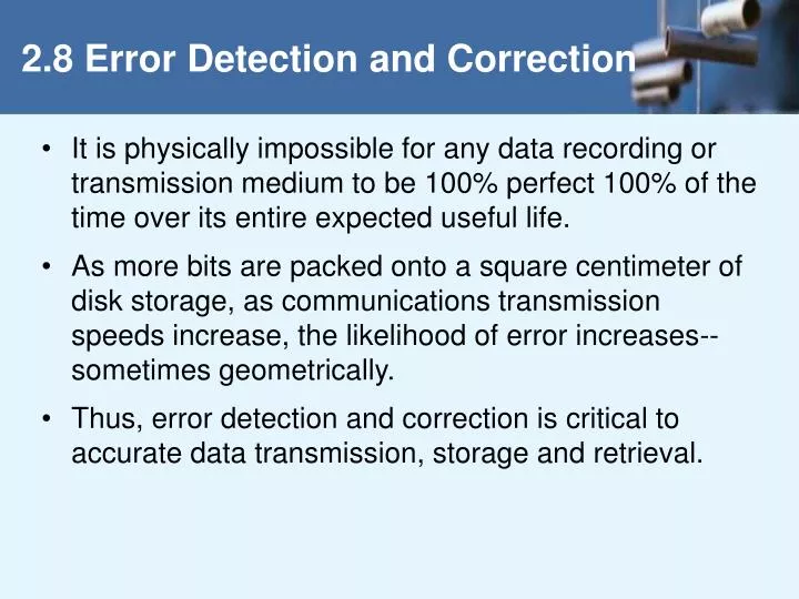
2.8 Error Detection and Correction • It is physically impossible for any data recording or transmission medium to be 100% perfect 100% of the time over its entire expected useful life. • As more bits are packed onto a square centimeter of disk storage, as communications transmission speeds increase, the likelihood of error increases-- sometimes geometrically. • Thus, error detection and correction is critical to accurate data transmission, storage and retrieval.
2.8 Error Detection and Correction • Check digits, appended to the end of a long number can provide some protection against data input errors. • The last character of UPC barcodes and ISBNs are check digits. • Longer data streams require more economical and sophisticated error detection mechanisms. • Cyclic redundancy checking (CRC) codes provide error detection for large blocks of data.
2.8 Error Detection and Correction • Checksums and CRCs are examples of systematic error detection. • In systematic error detection a group of error control bits is appended to the end of the block of transmitted data. • This group of bits is called a syndrome. • CRCs are polynomials over the modulo 2 arithmetic field. The mathematical theory behind modulo 2 polynomials is beyond our scope. However, we can easily work with it without knowing its theoretical underpinnings.
2.8 Error Detection and Correction • Modulo 2 arithmetic works like clock arithmetic. • In clock arithmetic, if we add 2 hours to 11:00, we get 1:00. • In modulo 2 arithmetic if we add 1 to 1, we get 0. The addition rules couldn’t be simpler: 0 + 0 = 0 0 + 1 = 1 1 + 0 = 1 1 + 1 = 0 You will fully understand why modulo 2 arithmetic is so handy after you study digital circuits in Chapter 3.
Find the quotient and remainder when 1111101 is divided by 1101 in modulo 2 arithmetic. As with traditional division, we note that the dividend is divisible once by the divisor. We place the divisor under the dividend and perform modulo 2 subtraction. 2.8 Error Detection and Correction
Find the quotient and remainder when 1111101 is divided by 1101 in modulo 2 arithmetic… Now we bring down the next bit of the dividend. We see that 00101 is not divisible by 1101. So we place a zero in the quotient. 2.8 Error Detection and Correction
Find the quotient and remainder when 1111101 is divided by 1101 in modulo 2 arithmetic… 1010 is divisible by 1101 in modulo 2. We perform the modulo 2 subtraction. 2.8 Error Detection and Correction
Find the quotient and remainder when 1111101 is divided by 1101 in modulo 2 arithmetic… We find the quotient is 1011, and the remainder is 0010. This procedure is very useful to us in calculating CRC syndromes. 2.8 Error Detection and Correction Note: The divisor in this example corresponds to a modulo 2 polynomial: X 3 + X 2 + 1.
2.8 Error Detection and Correction • Suppose we want to transmit the information string: 1111101. • The receiver and sender decide to use the (arbitrary) polynomial pattern, 1101. • The information string is shifted left by one position less than the number of positions in the divisor. • The remainder is found through modulo 2 division (at right) and added to the information string: 1111101000 + 111 = 1111101111.
If no bits are lost or corrupted, dividing the received information string by the agreed upon pattern will give a remainder of zero. We see this is so in the calculation at the right. Real applications use longer polynomials to cover larger information strings. Some of the standard poly-nomials are listed in the text. 2.8 Error Detection and Correction
2.8 Error Detection and Correction • Data transmission errors are easy to fix once an error is detected. • Just ask the sender to transmit the data again. • In computer memory and data storage, however, this cannot be done. • Too often the only copy of something important is in memory or on disk. • Thus, to provide data integrity over the long term, error correcting codes are required.
2.8 Error Detection and Correction • Hamming codes and Reed-Soloman codes are two important error correcting codes. • Reed-Soloman codes are particularly useful in correcting burst errors that occur when a series of adjacent bits are damaged. • Because CD-ROMs are easily scratched, they employ a type of Reed-Soloman error correction. • Because the mathematics of Hamming codes is much simpler than Reed-Soloman, we discuss Hamming codes in detail.
2.8 Error Detection and Correction • Hamming codes are code words formed by adding redundant check bits, or parity bits, to a data word. • The Hamming distance between two code words is the number of bits in which two code words differ. • The minimum Hamming distance for a code is the smallest Hamming distance between all pairs of words in the code. This pair of bytes has a Hamming distance of 3:
2.8 Error Detection and Correction • The minimum Hamming distance for a code, D(min), determines its error detecting and error correcting capability. • For any code word, X, to be interpreted as a different valid code word, Y, at least D(min) single-bit errors must occur in X. • Thus, to detect k (or fewer) single-bit errors, the code must have a Hamming distance of D(min) = k + 1.
2.8 Error Detection and Correction • Hamming codes can detectD(min) - 1 errors and correct errors • Thus, a Hamming distance of 2k + 1 is required to be able to correct k errors in any data word. • Hamming distance is provided by adding a suitable number of parity bits to a data word.
2.8 Error Detection and Correction • Suppose we have a set of n-bit code words consisting of m data bits and r (redundant) parity bits. • An error could occur in any of the n bits, so each code word can be associated with n erroneous words at a Hamming distance of 1. • Therefore,we have n + 1 bit patterns for each code word: one valid code word, and n erroneous words.
2.8 Error Detection and Correction • With n-bit code words, we have 2 n possible code words consisting of 2 m data bits (where n = m + r). • This gives us the inequality: (n + 1) 2 m 2 n • Because n = m + r, we can rewrite the inequality as: (m + r + 1) 2 m 2 m + r or (m + r + 1) 2 r • This inequality gives us a lower limit on the number of check bits that we need in our code words.
2.8 Error Detection and Correction • Suppose we have data words of length m = 4. Then: (4 + r + 1) 2 r implies that r must be greater than or equal to 3. • This means to build a code with 4-bit data words that will correct single-bit errors, we must add 3 check bits. • Finding the number of check bits is the hard part. The rest is easy.
2.8 Error Detection and Correction • Suppose we have data words of length m = 8. Then: (8 + r + 1) 2 r implies that r must be greater than or equal to 4. • This means to build a code with 8-bit data words that will correct single-bit errors, we must add 4 check bits, creating code words of length 12. • So how do we assign values to these check bits?
2.8 Error Detection and Correction • With code words of length 12, we observe that each of the digits, 1 though 12, can be expressed in powers of 2. Thus: 1 = 2 0 5 = 2 2 + 2 0 9 = 2 3 + 2 0 2 = 2 1 6 = 2 2 + 2 1 10 = 2 3 + 2 1 3 = 2 1 + 2 0 7 = 2 2 + 2 1 + 2 0 11 = 2 3 + 2 1 + 2 0 4 = 2 2 8 = 2 3 12 = 2 3 + 2 2 • 1 (= 20) contributes to all of the odd-numbered digits. • 2 (= 21) contributes to the digits, 2, 3, 6, 7, 10, and 11. • . . . And so forth . . . • We can use this idea in the creation of our check bits.
2.8 Error Detection and Correction • Using our code words of length 12, number each bit position starting with 1 in the low-order bit. • Each bit position corresponding to an even power of 2 will be occupied by a check bit. • These check bits contain the parity of each bit position for which it participates in the sum.
2.8 Error Detection and Correction • Since 2 (= 21) contributes to the digits, 2, 3, 6, 7, 10, and 11. Position 2 will contain the parity for bits 3, 6, 7, 10, and 11. • When we use even parity, this is the modulo 2 sum of the participating bit values. • For the bit values shown, we have a parity value of 0 in the second bit position. What are the values for the other parity bits?
2.8 Error Detection and Correction • The completed code word is shown above. • Bit 1checks the digits, 3, 5, 7, 9, and 11, so its value is 1. • Bit 4 checks the digits, 5, 6, 7, and 12, so its value is 1. • Bit 8 checks the digits, 9, 10, 11, and 12, so its value is also 1. • Using the Hamming algorithm, we can not only detect single bit errors in this code word, but also correct them!
2.8 Error Detection and Correction • Suppose an error occurs in bit 5, as shown above. Our parity bit values are: • Bit 1 checks digits, 3, 5, 7, 9, and 11. Its value is 1, but should be zero. • Bit 2 checks digits 2, 3, 6, 7, 10, and 11. The zero is correct. • Bit 4 checks digits, 5, 6, 7, and 12. Its value is 1, but should be zero. • Bit 8 checks digits, 9, 10, 11, and 12. This bit is correct.
2.8 Error Detection and Correction • We have erroneous bits in positions 1 and 4. • With two parity bits that don’t check, we know that the error is in the data, and not in a parity bit. • Which data bits are in error? We find out by adding the bit positions of the erroneous bits. • Simply, 1 + 4 = 5. This tells us that the error is in bit 5. If we change bit 5 to a 1, all parity bits check and our data is restored.