Download
1 / 33
360 likes | 958 Vues
High Brightness Remote Controlled White LED Bulb Group 27 Tzong-Yu Chan Justin Czarnowski April 30 th , 2009 Introduction High brightness LED light fixture could replace current commercially available white LED light bulbs which are about 300 lumens

E N D
High Brightness Remote Controlled White LED Bulb Group 27 Tzong-Yu Chan Justin Czarnowski April 30th, 2009
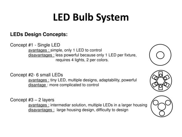
Introduction • High brightness LED light fixture could replace current commercially available white LED light bulbs which are about 300 lumens • The RF control feature allows user to control multiple light bulbs simultaneously
Features • High brightness light output equivalent to 100W incandescent light bulb (1700 lm) • RF wireless control • on/off • brightness dimming • Compatible with 120Vac from the outlet • Low power consumption, high reliability
High Brightness Remote Controlled White LED Bulb Power Supply LED units Receiver Remote Control
System Overview • Hardware: • Power Supply, RF Receiver, Dimming Unit, LED Light String, RF Transmitter • Software: • A/D and serial transmission code for remote PIC • Serial reception and PWM output code for receiver PIC
System Overview Power Supply Circuit LED Current Driver Heat Dissipater Bridge rectifier AC Power Source Power Converter PIC LED Circuit RF Receiver Wireless Remote RF Transmitter RF Transmitter 9V Battery 5V regulator Potentiometer and switch PIC
Hardware Overview • Power Supply • Take 120Vac power and convert to stable maximum 33 Vdc and 1 Amp • Transfomerless to reduce space and weight • Dimmer Unit • Change the amount of current going through the LEDs by varying the PWM duty cycle • RF Receiver & Transmitter • Allow user to control the light bulb remotely
Power Supply • Can supply up to 33Vdc to the LED circuit • Transformerless • Maximum current: 1Amp • 120Vac input directly from the wall outlet
Tranformerless Power Supply • Resistive Transfomerless Power Supply
Tranformerless Power Supply • Capacitive Transfomerless Power Supply
Tranformerless Power Supply • MOSFET Gate Controlled Transfomerless Power Supply Source: Supertex Application Note AN-H52
HV9931 • Fixed frequency PWM controller IC designed to control LEDs • Input voltage: 0~470V Source: Supertex Application Note AN-H52
Power Supply Source: Supertex Application Note AN-H52
Wireless Remote Control Objectives: • Operate up to 30 feet away from bulb • Line-of-sight not required • On/off and dimming capability • Predictable behavior when out of range
Wireless Remote Control Design: • Use RF transmission: Linx LC TX/RX pair • Remote PIC captures analog brightness value as an 8-bit digital value using ADC • 8-bit value transmitted wirelessly via Linx chips • Receiver PIC outputs PWM signal with duty cycle corresponding to 8-bit value
Wireless Remote Receiver Side Wireless Remote RF Transmitter RF Transmitter 9V Battery 5V regulator RF Receiver PIC Potentiometer and switch PIC to LED current driver…
Wireless Remote Schematic Voltage Regulator PIC RF Transmitter
Wireless Remote Receiver Remote Linx RF receiver Linx RF transmitter PWM output to LED current driver Brightness control potentiometer
RF transmission Baud rate = 9600 bps => 104us period Data input to transmitter (remote) Data output from receiver • Data matches -- wireless operation confirmed! • Wireless range only about 3 inches…
RF transmission verification • 8-bit brightness value is padded with leading and trailing “magic bytes” • Receiver only changes PWM duty cycle (brightness) if magic bytes are correct • Ensures predictable bulb operation even when remote goes out of range, loses power, etc.
PWM signal • Receiver PIC converts the 8-bit data into a PWM duty cycle percentage • PWM signal controls LED current driver which in turn controls brightness • The resulting brightness of the LED bulb is proportional to the duty cycle of the PWM signal PIC (receiver) PWM signal Serial data (8-bit)
25% 2% T = 20uS 75% 98% 50% Duty cycle = 100% (maximum brightness) PWM signal Duty cycle = 0% (completely dark)
Challenges • Originally intended to use MAX611 chip to convert 120 VAC to +5 VDC for powering Linx chip and PIC on receiver side • MAX611 is no longer available • Workaround: use 9V battery on receiver for demonstration purposes
Potential solution: BIAS Power BPI 200-05-00 • Requires minimal redesign of receiver circuit • Would require large quantity order Source: www.biaspower.com
LEDs • Cree XR-E R2 bin • Brightest commercially- available single LED • 228 lumens output at 1000 mA input current • Forward voltage ≈ 3.7 V • Star heat sink for heat dissipation
LEDs • 100W incandescent bulb output: ≈1700 lumens • (228 lumens/LED) x (10 LEDs) = 2280 lumens!
XR-E R2 performance Source: “LED Flux Spreadsheet.” Adam Royall Smith
Actual Performance • LED power supply does not output as much current as designed • Designed to output 1000mA but only outputs 100mA average! • LEDs relatively dim…
Actual Performance • Actual maximum output is only 40 lm/LED • Total max. output is only 400 lm • Falls short of design goals
Successes and Failures Failures: RF range only a few inches Very low current output Underperformance of current driver circuit caused low brightness Brightness control not smooth for output of high brightness LEDs Successes: RF communication functional Transformerless LED driver Obtained high brightness and high efficiency LEDs Smooth A/D conversion on remote PIC Receiving PIC decodes data and outputs appropriate PWM signal
SWOT Analysis • Weaknesses • Limited wireless range • Low brightness due to current driver circuit • High cost • Buzzing sound at high brightness • Strengths • Low power consumption • Transformerless • High brightness / high efficiency LEDs • Wireless control • Dimming capability • Opportunities • Potential to replace incandescent bulb • Could be used in hard-to-service areas due to longer lifetime • Threats • Not isolated from AC line • Undervoltage condition
Sources • http://www.cree.com/products/pdf/XLamp7090XR-E.pdf • http://www.biaspower.com/ • “LED Flux Spreadsheet.” Adam Royall Smith http://filebox.vt.edu/users/adsmith4/Lights/Emitter%20Flux%20Datacalc.xls • http://www.linxtechnologies.com/Products/RF-Modules/LC-Series-Low-Cost-Transmitter-and-Receiver-Modules/ • www.selectronic.fr/includes_selectronic/pdf/Maxim/MAX_611.pdf • Supertex Application Note AN-H52 www.supertex.com/pdf/app_notes/AN-H52.pdf • Supertex Unity Power Factor LED Lamp Driver Datasheet www.supertex.com/pdf/datasheets/HV9931.pdf • “The Nature of Light.” http://www.ccri.edu/physics/keefe/light.htm