Download
1 / 34
340 likes | 736 Vues
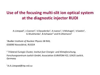
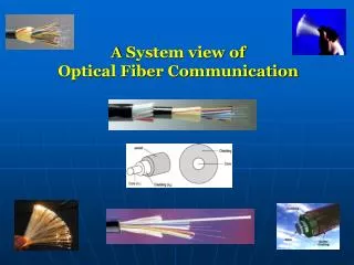
Why optical satellite communication? Extremely large bandwidth (5 THz for 200fs optical ... The pointing systems for laser satellite communication suffer during tracking from ...

E N D
Slide 5:Full use of the capacity of optical system
TRAFFIC TYPE BIT RATE (Mb/s) Voice 0.064 Data 0.01-10 High Fidelity Audio 1.0 Teleconferencing 1.5 Entertainment Video 50-150 1. Wire Pair 2. Coax Cable 3. Waveguide 4. Single Mode Fiber Hybrid WDM/TDM gives flexible, cost-effective solution to the opto-electronic bottleneck problem
Other Spatial Light Modulators Fixed Mask, Holographic, Real-time Holographic Phase and Amplitude; no pixels; no wire LCM-Arrays Phase and Amplitude; pixels; multi-line wires Deformable Mirror Phase; no pixels; multi-line wires Programmable Pulse Shaping Using Liquid Crystal Modulator (LCM) Array Same 4f configuration as the AOM pulse shaper Using the LCM array, multiple lines attached to the pixels Most of time phase only or phase-and-amplitude (using two sets of 4f system or two sets of LCM arrays. Using the liquid crystal to change the polarization of lights therefore the phase of the input pulse. Typically 128 pixels on 100 mm centers; up to 512 pixels reported. Reprogramming time > 10 ms Low attenuation Demonstrated to below 10 fs Phase and amplitude response must be calibrated Chirped Pulse WDM of Lucent Tech. Principles: A mode-lock laser ~150 fs, using fiber to stretch the pulse to ~30 ns and spectrum is spread in this time range, using fast EO modulator (8 GHz) to modulate the stretched pulse and create about 300 WDM channels Advantages: High density WDM, individual programmable bandwidth for each WDM channel Disadvantages: Strong time wavelength coupling Programmable Pulse Shapers: Movable and Deformable Mirrors Using the same optical setup, instead of AOM or LCM, a Mirror was placed in the center Fourier Plane. Pivoting Mirror provides a linear spectral phase shift, hence a delay! Spectral phase only control Reprogramming time ~ 1 msec Low attenuation Continuous spatial modulation, Array-Waveguide-grating Pulse Shaper A double arrayed waveguide grating with a spatial phase Filter forms a nearly integrated pulse shaper Has been demonstrated fro fixed dispersion slope compensation For 2*40 WDM channels in C and L bands simultaneously. Combine WDM and TDM Synthesis of shaped fs optical pulses through shaped ms RF pulses Arbitrary spectrum modulation (both phase and amplidue offers possibilities for any encoding scheme (ASK, PSK, FSK ...) High fidelity amplification achievable using standard techniques Viewing the pulse shaper as a DSP instrument (Time to spatial dispersed frequency component) FFT AOM Modulator RF Mixer (spatial dispersed frequency component to time again) FFT (1) (2) (3) At (1), the input ultrafast pulse contains the whole spectrum at the same beam, At (2), different colors are spread in spatial domain, the beam at different location will have less spectrum component; the corresponding pulse duration is longer. At (3), combined into the same beam again, if there is no pattern put into the pulse, it will correspond to the input pulse; if there are any phase mask to the AOM, the pulse will spreading depends on the FT of the pattern imposed on the AOM Synthesis of a perfect pulse in time domain Target 5 pulse sequence: ???? constant, Linear ????, Quadratic ????, Cubic ????, Quartic ???? Example of what the AOM can create: 3 Experimental Theoretical Constant amplitude, phase only modulated RF waveforms ????: constant, Linear, Quadratic, Cubic, Quartic Spectral phase resolution A phase resolution 0.1 radian only perturbs shaped pulse slightly Constant amplitude, phase only modulated RF waveforms Applications of AOM spectral encoder Components level Channel Equalization Tunable Dispersion Compensation Adaptive phase feedback System level DWDM/TDM Network Spectrum phase and amplitude control implemented via diffraction from a modulated traveling acoustic wave. Immunity to EMI No Cross-Talk Between Wires Difficult to Tap - High Security Light Weight and Small Cable Size and compact system No Ground-Potential Difference Currents Advantage of Ultrafast Communication Optical Satellite communication Traditional optical point to point communication One or a few channels only, low-powered infrared lasers AirFiber (Nortel Networks), claims to have a product that, when deployed throughout a metropolitan area, creates a meshed architecture that can transmit data in up to four directions at 622 Mbit/s simultaneously in a distance range between 200 and 450 meters. TeraBeam Corp (Lucent Technologies Inc.), can be used as a point-to-multipoint product that uses a hub-and-spoke architecture. it can achieve data rates of 100 Mbit/s. 1-2 Km. Proposed optical point to point satellite communication WDM functionality: Power equalization, Channel Add-Drop, etc. A compact systemSlide 18:Typical Experimental Setup
SErF AWG Pulse Picker Driver PC Scope GPIB (GPIB) CCD Scope (Or OSA) PCI RF circuit
Adaptive, automatic equalization by Pulse shaper Fast, real-time correction Dynamical Equalization by Pulse Shaper Demonstration of DWDM Transmission Information transmission Tb/s transmission speed: free space/ fiber pigtailed Benchmark image transmission No bit error found System and Architecture E/O High-ratio Data Compression Hybrid TDM/WDM Architecture Wavelength Domain CDMA The system and the componentsSlide 23:Satellite Using AOM Pulse Shaper
LAN A LAN B Satellite node Satellite node Model of the hybrid network topology allowing fast access to remote sites in different Location at earth. The interfaces provided by the geo-stationary satellites are connected by the ultra-high speed optical satellite link.
Spectral Encoder: Device Types Optical Packaging LCD, commercial available AWG-fiber device, commercial available AOM, commercial available Photonic circuits Commercial available (In view of the properties of the atmosphere, traditionally two windows are used: optical window, wavelengths from 300 - 14000 nm microwave window, wavelengths from 1 mm - 1 m. ) Light Sources, proposed either 800 nm or 1500 nm An existing Optical Satellite Forward and Reversed Links Forward Link Transmission Modes Return Link Transmission Modes Laser ISLs (0.83/ 0.51 micron). A 7.5 cm telescope with 14 mW GaAlAs diode transmitter clock laser (~1 ps) 1XN -33 dB Signal Laser ~ 150 fs P > 17 dBm SNR> 30 dB N X N Star Coupler L =-33-2 dB F = 0 Tracking One Node BER TDM Switching Pre Amp The Network Architecture Traditional Multiplexing Methods TDMA WDMA WD-CDMA Why Wavelength Domain Optical Bandwidth(5 THz) v.s. Electronic Speed (~1GHz) O/E Interface needs High Ratio (104) Data Compression Implementation of WD-CDMA Spectral Encoder (Spread Time) Amplitude Only (Optical Codes, PPM) Phase Only (Binary Codes) CDMA as the coding scheme-WD-CDMA New Protocol WD-CDMA Pulse Shaping WDM: hundreds time increase of Date Transmission rate (DTR) combined with TDM Pulse Shaping CDM: hundreds time increase of Channel number combined with TDM High Spectrum Efficiency Time Wavelength Wavelength Intensity In order to transmit data at rates of up to 10 gigabits/second over distances of up to 40 000 km, optical terminals has to be developed, which can perform two-way communication with LEOs (Low Earth Orbiters), GEOs (Geostationary Satellites) and ground stations. These Laser Communication Terminals (LCT) will be developed by the research groups in cooperation with industrial partners. For several years, the components for space have to meet high quality standards with respect to data accuracy and system stability. In order to ensure that these criteria are fulfilled, components must be tested extensively on a system and subsystem level. The proposed system will use solid state components. Challenges faced Tracking An important aspect in satellite optical communication is to obtain minimum bit error rate (BER) using minimum power. This aim can be achieved with very small transmitter beam divergence angles. The disadvantages of too narrow divergence angle is that the transmitter beam may sometimes miss the receiver satellite, due to pointing vibrations. In order to communicate between them, the transmitter satellite must track the beacon of the receiver satellite and point the information optical beam in its direction. The pointing systems for laser satellite communication suffer during tracking from vibration due to electronic noise, background radiation from interstellar objects such as Sun, Moon, Earth, and Stars in the tracking field of view, and mechanical impact from satellite internal and external sources. Due to vibrations the receiver receives less power. This effect limits the system bandwidth for given bit error rate (BER). This interdisciplinary research includes the following areas: satellites engineering, vibration source and effect, communcation, laser, optical communication and tracking. The problem is further complicated due to vibration of the pointing system caused by two stochastic fundamental mechanisms 1) tracking noise created by the electrooptic tracker and 2) vibrations created by internal and external mechanical mechanisms. The vibrations displace the transmitted beam in the receiver plane. Such movement of the transmitted beam in the receiver plane decreases the average received signal which increases the bit error rate. It was believed that vibrations limit dramatically communication system performance. Pulse shaping and measurement techniques have applications in high-speed satellite telecommunications. System Prospects: TDM/WDM, Spectral-encoding CDMA, etc.. Various Component and Functionality: Data compression, WDM channel equalizations, etc. Immediate applications of spectral interference and phase retrieval measurement techniques.Slide 34:Conclusion and following work
Components level Introducing femtosecond pulse shaping Channel Equalization System level Optical Satellite Communication and information transmission Following work Developing commercial system for satellite communication Novel techniques like Pulse Shaping WDM and Pulse Shaping CDM can achieve 2Tb/s DTR with commercially available components: