Download
1 / 43
440 likes | 575 Vues
SOME ASPECTS CONTRIBUTING TO WASTE-TO-ENERGY AND ENVIRONMENTAL PROTECTION. Petr Stehlik Technical University of Brno, Czech Republic. INTRODUCTION. Present situation: Energy saving and pollution prevention = priorities Sustainability concepts = complex problem

E N D
SOME ASPECTS CONTRIBUTING TO WASTE-TO-ENERGY AND ENVIRONMENTAL PROTECTION Petr StehlikTechnical University of Brno, Czech Republic
INTRODUCTION Present situation: • Energy saving and pollution prevention = priorities • Sustainability concepts = complex problem • Renewable energy sources e.g. Waste-to-Energy
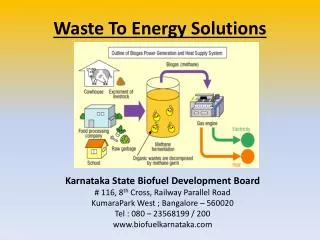
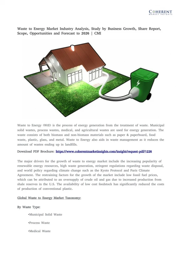
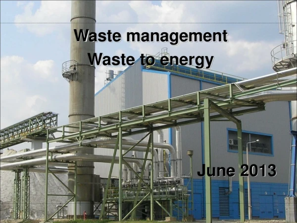
WASTE-TO-ENERGY • Waste-to-energy (WTE) technology = = thermal processing of wastesincluding energy utilization • WTE systems clean, reliable and renewable energy Combustion of wastes (incineration) generation of heat steam sold electricity sold
WASTE-TO-ENERGY Environmental Benefit: • WTE prevents the release of greenhouse gases (CH4, CO2, NOX, VOC) • Dual benefit: clean source of electricity and clean waste disposal Economic Benefit: • Renewable energy • Reduction of need to landfill municipal waste
WASTE-TO-ENERGY Reasons for Investment to WTE Sources of renewable energy for electric generation Note: Source - Renewable Energy Annual 1998 - U.S.Department of Energy, Energy Information Administration
SUSTAINABLE DEVELOPMENT, EFFICIENT DESIGN AND RENEWABLE ENERGY SOURCES IN THE PROCESS INDUSTRY The following criteria can play a decisive role: • economic and efficient process design • global heat transfer intensification (design of heat exchanger network for maximum energy recovery) • efficient selection of utilities including combined heat and power systems (co-generation) wherever possible • using waste-to-energy systems and/or their combination with conventional ones as much as possible
SUSTAINABLE DEVELOPMENT, EFFICIENT DESIGN AND RENEWABLE ENERGY SOURCES IN THE PROCESS INDUSTRY Criteria (continued): • design of efficient equipment (reactors, separators, heat exchangers, utility systems etc.) • local heat transfer intensification (selection and design of individual heat exchangers including heat transfer enhancement) and various other criteria
IMPROVED PROCESS AND EQUIPMENT DESIGN Research domains in improved process and equipment design
IMPROVED PROCESS AND EQUIPMENT DESIGN(continued) EXPERIENCE IN DESIGN AND OPERATION SOPHISTICATED APPROACH (ADVANCED COMPUTATIONAL METHODS) IMPROVED DESIGN = + Improved Process Design • Process integration (e.g. Pinch Analysis) • MER design • Utilities selection • Total Site Integration
IMPROVED PROCESS AND EQUIPMENT DESIGN(continued) Improved Equipment Design Examples New type of Shell-and-Tube Heat Exchanger Retrofit of an industrial process: adding a few more heat exchangers energy saving increased pressure losses greater pumping power FIND A SOLUTION !
IMPROVED PROCESS AND EQUIPMENT DESIGN(continued) Conventional heat exchanger (segmental baffles) Helixchanger (helical baffles) Comparison Example: p = 44 kPa (crude oil preheating,1 MW, 90t/hr) p = 17 kPa Result: 60% reduction of operating cost 6.3% reduction of total cost
IMPROVED PROCESS AND EQUIPMENT DESIGN(continued) Optimization of Plate Type Heat Exchanger Minimization of total cost (utilizing relation „p - h.t.c.”) Obtaining optimum dimensions Example: Industrial unit for the thermal treatment of polluting hydrocarbons of synthetic solvents contained in air (4.52 MW) Result: up to 14% reduction of annual total cost can be achieved
THERMAL TREATMENT OF HAZARDOUS INDUSTRIAL WASTES AND WASTE-TO-ENERGY SYSTEMS • Originally: • disposal of wastes (treatment of wastes) • At present: • waste processing (waste-to-energy systems) • recovering heat (generating steam & electricity • preheating purposes (reduced fuel demand) • processing of residues (vitrification)
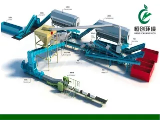
THERMAL TREATMENT OF HAZARDOUS INDUSTRIAL WASTES AND WASTE-TO-ENERGY SYSTEMS - continued EXAMPLES Multi-purpose incinerator for processing solid and liquid wastes
Legend: 1 - screw conveyor 4 - secondary combustion chamber 2 - fluidized bed reactor 5 - heat recovery steam generator 3 - cyclone 6 - steam turbine 7 - off-gas cleaning system 8 - stack Legend: 1 - screw conveyor 4 - heat recovery steam generator 2 - rotary kiln 5 - steam turbine 3 - secondary combustion chamber 6 - off-gas cleaning system 7 – stack 4 4 5 7 8 3 1 2 3 7 6 2 6 5 natural gas natural gas Incineration Gasification Combustion ~ INCINERATION VS. GASIFICATION - COMPARISON Rotary kiln vs. gasification reactor flue gas solid waste flue gas superheated steam feed water air air natural gas Storage waste feeding Heat recovery Off-gas cleaning
INCINERATION VS. GASIFICATION - COMPARISON • Discussion of comparisonÞ in the case of gasification: • Generating gaseous products at the first stage outlet up to 10 times lower Þ aspects influencing operating and investment costs • Considerably lower consumption of auxiliary fuel (natural gas) Þ autothermal regime • Reduced size of the afterburner chamber compared to that necessary for a comparable oxidation incineration plant
INCINERATION VS. GASIFICATION - COMPARISON • Discussion of comparisonÞ in the case of gasification: • Lower specific volume of gas produced Þ reduction in size of flue gas heat utilization and off-gas cleaning systems Þ reduction of investment and operating costs of the flue gas blower • Lower production of steam (proportional to the volume of flue gas produced) • Disadvantage of gasification technology: Treatment of wastes by crushing/shredding and by homogenization before feeding into the reactor
Gas output 34 250 Nm3/hr Gas output 3 570 Nm3/hr INCINERATION VS. GASIFICATION - COMPARISON Comparison of the two alternatives SCC Auxiliary fuel consumption 12 Nm3/hr Secondary combustion chamber Auxiliary fuel consumption 602 Nm3/hr Alternative with a rotary kiln Alternative with a gasification reactor
THERMAL PROCESSING OF SLUDGE FROM PULP PRODUCTION Incinerator for thermal treatment of sludge from pulp production
COPMLETE RETROFIT Result: Modern up-to-date plant
RETROFIT: FIRST STAGE Incinerator capacity vs. dry matter content in sludge
THERMAL TREATMENT OF HAZARDOUS INDUSTRIAL WASTES AND WASTE-TO-ENERGY SYSTEMS - continued EXAMPLES Incineration unit of sludge generated in the pulp and paper plant
RETROFIT: THIRD STAGE ECONOMICS ASPECTS Investment return depending on MG/NG ratio The curve is valid for: considering depreciation, loan interest, inflation etc. annual operation 7000 hours nominal burners duty 6.4 MW (2.4 MW for fluidized bed combustion chamber and 4.0 MW for secondary combustion chamber) investment of $ 250,000
RETROFIT: THIRD STAGE ECONOMICS ASPECTS Major saving of operational cost in terms of price of 1MW of energy: price (MG) 2/3 price (NG) MG – mining gas NG – natural gas Possible saving of cost for fuel
DUAL BURNER ORIGINAL DESIGN: • One fuel • Two stages of fuel and two stages of combustion air LATER: • Dual burner = mining gas + natural gas(primary fuel) (auxiliary fuel) INTERESTING APPLICATION: • Secondary combustion chamber in the incineration plant for thermal treatment of sludge from pulp production (see above)
Utilisation of Alternative Fuels in Cement and Lime Making Industries • Current situation: • alternative fuels (wastes) used mainly in cement kilns • use of alternative fuels in lime production is less applied due to potential impact on product quality • practical issues of the application include waste specification, way of feeding, product quality, and emission levels
PERFORMANCE TEST • Feeding of alternative fuel: • composition: mixture of crushed plastic, textile, paper • pneumatic conveying into the kiln by special nozzle beside main burner • heating value: 24 GJ/t (compared to 39.5 GJ/t of the baseline fuel)
PERFORMANCE TEST • Test site: • limekiln, production capacity 370 t/d • rotary kiln • baseline feed: black oil (~1.8 t/h) • goal: to feed 0.5 t/h of waste and validate product quality, emission levels, and the potential for savings
PERFORMANCE TEST Alternative fuel
PERFORMANCE TEST Double-tube feeder
PERFORMANCE TEST • Test evaluation:
PERFORMANCE TEST • Conclusions: • Substitution of a part of the conventional fuel to cover partially heat supply demands of cement factories • It is possible to achieve 10 to 20% of the overall energy demand of the rotary kilns • In the case of limekilns (where substitution of the noble fuels is often hindered by higher requirements on the final product quality) up to 17% of the primary fuel without notable impact on the lime quality was achieved
CEMENT FACTORY • Potential for savings in a cement factory with the same alternative fuel:
CEMENT FACTORY • Potential for savings in a cement factory with the same alternative fuel:
THERMAL TREATMENT OF HAZARDOUS INDUSTRIAL WASTES AND WASTE-TO-ENERGY SYSTEMS - continued Waste-to-Energy Plant Structure Processing of wastes of wide spectrum WTE Plant Structure (mutual interconnection of main units ) WTE utility heat output - for various purposes (e.g. servicing district heating system, air conditioning, chilled water production, exporting steam to an industrial plant)
Air Natural Gas Water Flue/Exhaust Gas Flue/Exhaust Gas Combustion Turbine Gen - set Heat Recovery Steam Generator Steam Power to the Grid Steam Turbine Gen - set Heat Exporting Unit Steam from Flue Gas Heat Recovery Boiler Exported Heat
Incoming „Solid“ Waste Natural Gas Liquid Waste Air Air Close Coupled Gasifier Combustor Waterwide Flue Gas Heat Recovery Boiler Flue Gas Heat Recovery Boiler NaHCO3 Injection Assembly & Chemical Reactor NaHCO3 Injection Assembly & Chemical Reactor Ash Waste pretreament Rotary Kiln & Secondary Combustion Chamber Ash Flue Gas Water Water Steam to Steam Turbine Flue Gas Flue Gas Flue Gas to Fly Ash Separation Flue Gas Flue Gas Steam
Flue/Exhaust Gas Natural Gas Air Fly Ash Fly Ash Separation Fabric Filter Flue Gas Glass Products Flue/Exhaust Gas Air to Rotary Kiln & Secondary Combustion Chamber Fluidized Bed Sterilizing - Drying Unit Separated Fly Ash Vitrification Unit Selective Catalytic Reduction Facility Flue Gas Air Concentrated Waste Water Treatment Sludge Fertilizers Flue / Exhaust Gas
CONCLUSION It has been shown how various aspects of a process and equipment design can contribute to improving economic and environmental design. WTE systems provides us with clean, reliable and renewable energy. WTE systems = up-to-date technology + experience (know-how) + theoretical background Examples