Download
1 / 61
680 likes | 1.28k Vues
Medium Voltage Induction Motor Protection and Diagnostics. Yi Du Pinjia Zhang Prof. Thomas G. Habetler School of Electrical and Computer Engineering Georgia Institute of Technology Atlanta, GA. Medium Voltage Facilities. Medium Voltage Supply. Medium Voltage Laboratory. Outline.

E N D
Medium Voltage Induction Motor Protection and Diagnostics Yi Du Pinjia Zhang Prof. Thomas G. Habetler School of Electrical and Computer Engineering Georgia Institute of Technology Atlanta, GA
Outline • Introduction • Heat transfer inside Motors • Thermal Model-Based Approaches • Parameter Model-Based Approaches • Other Approaches
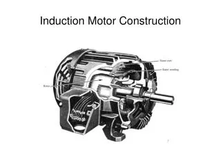
Medium voltage induction motors • Mostly used in the petroleum, chemical, mining and other industries, • Rated from 2300 V to 13200 V, • They are rotor limited during starting, and stator limited under overload.
Overload Protection • Malfunctions of these motors are very costly due to loss of productivity, • The winding insulation failure is a typical malfunction, which is often caused by overload.
Conventional Overload Relays • Conventional overload relays utilize simple thermal models and embedded temperature sensors. • Simple thermal models can not estimate the rotor temperature. • Disintegration of the connection, noise interference, and large time constant of the sensors often result in false alarm or trips.
Requirements • Track the thermodynamic behavior of the motor's stator and rotor under steady and transient state conditions. • It should also take into account the important differences in the thermal behavior due to the motor size and the type of construction and ventilation.
Possible Approaches • Higher order thermal model-based approaches Model the thermal behavior of the motor. The thermal parameters are calculated from the motor dimensions and offline experiments. This approach is robust, but measurements need be made for each motor. • Parameter-based approaches Estimate the temperature from the variation of the resistance of the stator and rotor. This method can respond to changes in the cooling conditions, and is accurate, but it is generally too sensitive.
Outline • Introduction • Heat Transfer inside Motors • Thermal Model-Based Approaches • Parameter Model-Based Approaches • Other Approaches
Motor Losses • The temperature rise inside a motor is caused by the losses accumulated in the motor.
Loss Segregations Loss segregation for 15Hp motor Compared with low power motors, high power motors have larger percentage of core loss and stray loss, and smaller percentage of copper loss. Therefore, the thermal model only considering copper loss is not suitable for large motors. Loss segregation for 200~2000Hp motors
Heat Transfer The heat transfer inside a motor can be classified into • Conduction - transfer of heat due to the temperature difference. Shaft – rotor iron – rotor winding, Stator winding – stator iron – Frame, … • Convection - transfer of heat due to the fluid motion. Frame - external air, stator/rotor– airgap, rotor – endcap air, ... • Radiation - transfer of heat by electromagnetic radiation. Radiation is ignored since the motor temperature is relatively low.
Thermal resistance and thermal capacitance • Thermal behavior of the motor can be analyzed by • Finite element methods (Time consuming) • Lumped-parameter thermal network, composed of thermal resistors, thermal capacitors and heat sources. • Some thermal resistances and thermal capacitances can be calculated directly from the motor dimensions. • Other thermal resistances are complex and can only be measured online. • Stator core to frame conduction resistance • Endwinding cooling resistance • Frame to ambient convection resistance
Thermal Network • Given the difficulties to calculate certain thermal parameters, detailed thermal models can not guarantee good accuracy. • Simplification of the thermal network is preferred for online monitoring. • On the other hand, the thermal network should be complex enough to estimate the hot spot temperature.
Outline • Introduction • Heat Transfer inside Motors • Thermal Model-Based Approaches • Parameter Model-Based Approaches • Other Approaches
Thermal Model-based Approaches • Use thermal network to model the thermal behavior of the motor. • The Motor is divided into homogenous components wherein each part has a uniform temperature and heat transfer coefficients. • The heat flow paths are determined and thermal resistors are added between the nodes. • Losses and thermal capacitors are allocated to each node.
First - order Thermal Model • Used in conventional relays for its simplicity, • Do not consider the rotor winding temperature, • The stator winding temperature is given by,
First - order Thermal Model • Thermal resistance Rth and thermal capacitance Cth can be directly calculated from the trip class t6x and the service factor SF. • Assume the loss Ploss equals the stator copper loss • Cth is calculated using the trip class and the winding insulation class.
First - order Thermal Model • Temperature rise is a complex combination of distributed thermal capacitances and resistances, single time constant is not enough. • Therefore, large margin is needed for safety and the motor is over protected. • The rotor temperature can not be monitored.
Second - order Thermal Model • Stator and rotor are modeled separately, • Model B eliminate the node while maintaining the same function. • Parameters are calculated from offline experiments Model A Model B
Second - order Thermal Model • Model C simplifies the rotor side, and less parameters are needed. • Second-order thermal model is a good tradeoff between accuracy and complexity. Model C
Higher - order Thermal Model • Model the hot spot, such as end windings, seperately. • The thermal model becomes complex and it is difficult to identify the parameters.
Outline • Introduction • Heat Transfer inside Motors • Thermal Model-Based Approaches • Parameter Model-Based Approaches • Other Approaches
Parameter-based Approaches Estimate the temperature from the variation of the stator winding resistance and the rotor bar resistance. k1 is 234.5 for 100% IACS conductivity copper It is an online method and can respond to changes in the cooling conditions.
Rotor Resistance • Rotor resistance can be calculated in the synchronous reference frame with the d-axis aligned with the stator current. Under the steady state, the rotor resistance, which is independent of the stator resistance, is given by • Rotor resistance can also be calculated in the stationary reference frame and rotor reference frame. • By these methods, the rotor resistance is independent of the stator resistance and is less sensitive to the parameter variations.
Stator Resistance • Stator resistance is generally calculated based on rotor resistance. • In the synchronous reference frame with the d-axis aligned with the stator current, the stator resistance is given by, • Rotor speed can be calculated from the stator current harmonics.
Outline • Introduction • Heat transfer inside Motors • Thermal Model-Based Approaches • Parameter Model-Based Approaches • Other Approaches
Neural Network - based Approaches • Neural networks have been proposed to estimate the stator resistance and rotor resistance. • The advantages are that they do not require the motor parameters and can be easily implemented. • The drawbacks are they are still sensitive to the parameter changes since the network is trained using the data based on certain parameters.
Hybrid Approaches • Combine thermal model – based approaches with parameter – based approaches, • Rotor temperature is estimated by parameter – based approaches since it is less sensitive to the parameter variations, • Stator temperature is monitored by thermal model – based approaches.
Signal Injection-based Approaches • The stator resistance is estimated from the dc components of the voltage and current. • Relatively accurate since it is not affected by the inductance of the motor. • It is intrusive and introduces torque oscillation.
Overview of Fault Diagnostics for MV Motors Induction Motor Fault Categories Distribution of MV Induction Motor Failures
OUTLINE • Overview of Fault Diagnostics for MV Motors • Bearing Failure and its Diagnostic • Stator Winding Inter-turn Fault and its Diagnostic • Rotor Fault and its Diagnostic • Broken Rotor Bar & End-Ring Faults and their Diagnostic • Rotor Eccentricity and its Diagnostic • Conclusions
Overview of Fault Diagnostics for MV Motors Induction Motor Fault Categories Distribution of MV Induction Motor Failures
Analysis of Fault Diagnostics for MV Motors Main differences between MV motors and small low-voltage motors: • High Insulation Requirement for Stator Winding: stator winding inter-turn fault • Large Output Torque: rotor and bearing- related mechanical faults • High Thermal Stress: stator insulation failure and rotor-related faults
Bearing Failure Monitoring Bearing failure is the most common fault for MV motors. Reasons for Bearing Failure • Electrical Stress: Stator, rotor or input voltage unbalance causes unbalanced magnetic flux, which induces shaft current, and potential voltage between bearing and ground. • Mechanical Stress: • Friction and rotor eccentricity can cause mechanical failure of bearings. • Thermal Stress: • Overheat causes the failure of lubricant, which lead to friction. Outer raceway Inner raceway Ball Cage
Bearing Failure Monitoring Classification of Bearing Failure: • Single Point Defects: • Outer raceway • Inner raceway • Ball • Cage • Generalized Roughness Existing Methods: • Standard vibration sensor method • Chemical analysis method • Temperature monitoring • Acoustic emission method • Sound pressure method • Current signature spectra method
Current signature spectra methods 1.Single point defects: • Wavelet method • Neural network clustering method • Adaptive time-frequency method • Park vector trajectory method • Other methods 2.Generalized roughness: • Mean spectrum deviation method Fundamentally: monitor the E-M torque harmonics corresponding to the mechanical vibration frequencies
Bearing Failure Monitoring is the power supply frequency; is the vibration frequency; is the corresponding stator current signature frequency. Challenges for MV motors For single point defects: • Poor Signal/Noise Ratio Due the large output torque, the torque vibration caused by bearing failure is more difficult to observe. So the low signal/noise ratio is a potential problem for current-based bearing diagnosis of large MV motors. For generalized roughness: • Separate measurement noise and bearing failure-related vibration noise