Download
1 / 18
180 likes | 503 Vues
NIRAD Data Package for the NASA WB-57. N on-dispersed I nfra R ed A irborne CO 2 D etector (NIRAD). Prepared by Darin Toohey University of Colorado, Boulder April 2004 Updated March 2005.

E N D
NIRAD Data Package for the NASA WB-57 Non-dispersed InfraRed Airborne CO2Detector (NIRAD) Prepared by Darin Toohey University of Colorado, Boulder April 2004 Updated March 2005
This package has been updated to account for a change in mounting of NIRAD into the rack of the right wing pod in order to make room for the new fast ozone instrument during PUMA (April/May 2005). The individual components of NIRAD are the same. However, they are now packaged into a single box that will be mounted to the left rear of the wing pod rack. • Major changes to NIRAD, reflected in the revised slides below, are: • Weight has been reduced 4 kg (~9 lb). New weight 66.5 lb • The instrument is contained in a single box rather than three separate components as previously. New dimensions 10”(w) x 24”(l) x 14” (h) • The box is mounted with six 10-32 cadmium plated stainless steel screws that are easily accessed for quicker installation and removal. New, simpler, structural calculation • There is now a single gas line connection (as opposed to the original three) to make/break during installation and removal. New, simpler, operating procedures • Minco heaters have been added to the gas-handling system to reduce changes in pressure regulator settings. New power diagram and specifications • No changes to pressure system
1. Payload Description Measurement: Carbon Dioxide (CO2) Method: Non-dispersed infrared absorption spectroscopy relative to a reference gas with known CO2 Instrument Details: Right wing pod, 66.5 lb, 10”x24”x14” (lwh), <250 W (28V aircraft power at <10 A) Sampling frequency: 10 Hz Accuracy: < 0.1% Precision: <0.03% at 10 Hz, <0.01% at 1 Hz, < 0.003% at 10 seconds NIRAD consists of three systems: (1) CO2 detector, (2) power and data acquisition, and (3) gas-handling. All three systems have flown previously. The CO2 detector was first flown in 1999 as part of CORE+ instrument during RISO and ACCENT and again in 2004 during PUMA-A. There have been no changes to the detector, other than inspection and routine maintenance. The power and data acquisition system were new for PUMA-A, and are flown here without change, other than to software. The gas-handling system is the same as that flown in May 2004, except that it is now packaged into a single box that contains the detector and power/data system. The detector is packaged in a vacuum housing to facilitate management of temperature and pressure. At power-up the housing is pumped down to ~300 hPa by one stage of a diaphragm pump and held at this pressure throughout the flight. Thus, at pressure altitudes < 300 hPa the pressure within the housing is above ambient. By design, if the pressure differential is significantly greater than about 5 psi, the O-ring seals leak. A redundant additional mechanical safety relief valve (set for ~15 psi or less) is placed on the housing. Two 1.2 L epoxy-coated, fiber-wrapped aluminum bottles (DOT rated and certified) are filled to ~1600 psi before flight with zero air doped with CO2. These ‘standards’ are sampled repeatedly during flight to provide an accurate standard for reference to the NOAA/CMDL CO2 scale. Two-stage regulators provide a service pressure of ~25-30 psig throughout flight. The bottles and regulators are backed with safety relief valves. The diaphragm pump is current-limited for a ‘soft start’ (that is, there is no electrical surge on startup, allowing for use of compact, highly efficient Vicor VI-100 DC/DC converters.
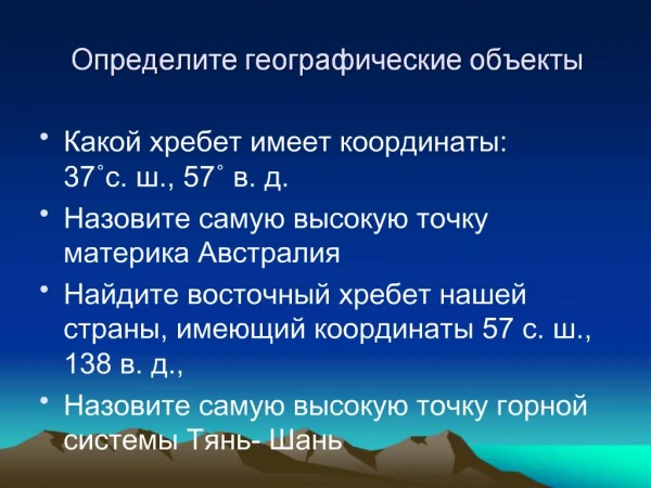
+15V 5V -15V 12V Instrument Schematic Electrical Outline } LiCor electronics and pressure controllers Astec DC/DC 100 W rating 20 W 24V Vicor VI-100 Pressure gauges and controllers 2 W 7805 7812 CO2 analyzer 10 W 28Vin 5V PC-104 DC/DC 100 W rating Computer + A/D System 15 W Vicor VI-100 Diaphragm pump 50 W Heaters 75 W
2. Structural Analysis (a) Itemized weight Component Weight, kg Weight, lb CO2 analyzer 7.00 15.4 diaphragm pump 4.10 9.0 MKS 248 Control valve 0.54 1.2 solenoid deck 0.58 1.3 gas standard 1w/relief valve 1.60 3.5 gas standard 2 w/relief valve 1.60 3.5 PC-104 computer stack 0.60 1.3 dc/dc converter 1 0.10 0.2 dc/dc converter 2 0.10 0.2 gas regulator 1w/relief valve 1.00 2.2 gas regulator2 w/relief valve 1.00 2.2 cables, gas lines, fittings 2.16 4.4 frame, structure, covers 9.55 21.0 inlet 0.50 1.0 Total 30.23 kg 66.5 lb
2. Structural Analysis (click on Excel spreadsheet for supporting calculations) (b) Issues There are two structural issues to consider for integration of NIRAD into the wing pod of the WB-57. The first issue involves the mounting of the individual components listed on the previous page into the box, the second involves mounting the box to the rack. These will be dealt with separately below. 1 - Mounting of individual components into the instrument box Due to small masses, nearly all components are mounted within the respective housings with high safety margins (factor of 10 or larger). The component with the lowest safety factor is the diaphragm pump, which weighs 10 lbs and is mounted with four #10 stainless steel bolts to a 1/8” thick aluminum plate that forms the bottom of the box. Viton rubber sheets are used between the lugs of the pump and the plate to dampen vibration, although the Vacubrand pump used here was selected for its extraordinarily low vibration. The bolts are secured into locking captive washers (cinch nuts). Structural analysis shows that all loads have safety margins of x5 or larger, the lowest being the vertical (up) load plus horizontal (forward/aft and left/right) overturning moments (margin = 10). Thus, it is determined that the pump is safely mounted to the box, and that all other components, which are smaller and lighter, do not represent safety issues. 2 – Mounting of box and frame to rack The instrument box is mounted to the rack with six #10 cadmium coated, stainless steel bolts. Structural analysis shown in the accompanying excel file indicates that the lowest safety margin (380-480%, or a factor of nearly 5 over nominal ratings) is for the flange bending (vertical load plus horizontal overturning moments). Flange shearout has a safety margin of over 700%, and all other margins are at least a factor of ten over nominal ratings.
Instrument Name: NIRAD AMPS Voltage Nominal Maximum Peak Inrush Notes 28 VDC 4.0 7.0 Values based on measurements in lab and estimates of pump performance versus pressure 115 VAC 60 HZ (Single Phase) 115 VAC 400 HZ (Single Phase) 115 VAC 400 HZ (Three Phase - A) 115 VAC 400 HZ (Three Phase - B) 115 VAC 400 HZ (Three Phase- C) 3. Electrical Load Analysis Maximum value will occur on ascent, immediately following power-up, where the pressure is largest and temperatures are lowest. This is due to loading of diaphragm pump and heaters. Nominal current draw will depend on cruise altitude – lower values pertaining to highest altitudes Momentary (< 0.1s) surges of ~0.3 A may occur due to valve switching at ~120 second intervals
4. Pressure/vacuum systems • NIRAD has three systems that fall under the category of pressure/vacuum (P/V) systems – flow system (P and V), gas handling system (P), and detector housing (P and V). These will be discussed separately below. • The flow system consists of a Vacuubrand MD VarioSP 4-stage diaphragm pump, two stages of which compress air to ~ 1000 hPa (15 psi) absolute pressure from ambient pressure under all flight conditions, and two stages that serve to pull air through the flow system ultimately venting to ambient air. A safety relief valve set to ~5 psig serves to limit potential over-pressure situations (see C below). All materials are capable of withstanding an overpressure of ~45 psig without damage. • The gas-handling system consists of two Structural Composites Industries (SCI) 1.2 L epoxy-coated fiber-wrapped Al bottles (ALT 296C-32449 and ALT296C-32479) both DOT-E 7277-3000). Bottles were recertified in April 2004. The bottles are filled with CO2-doped air to a service pressure of ~1600 psi before each flight, thus serving as standards for in-flight calibration. The bottles are backed with Nupro series R3A (177-R3A-K1-E) stainless steel safety relief valves that can be set at Ellington Field prior to use. • The detector vacuum housing is custom built from six 2024-T3 aluminum plates machined for reduced weight. Only the bottom plate is structural. The four side plates are welded together to provide an adequate vacuum seal. This weld is not structural. Viton O-rings seal the top and bottom plates to the rectangular sides of the housing. Vacuum is maintained by actively pumping on the sealed box, and any small leaks are compensated for by venting the flow through the LiCor analyzer into the box. At low altitudes, the housing is at a lower pressure than ambient. Above ~35,000 feet, the housing is maintained several psi above ambient pressure. At these low pressure differentials, the box remains sealed. However, laboratory tests in a bell jar (photos available upon request) show that the housing can withstand ~10-12 psig positive differential. However, under larger positive differentials the O-ring seal on the top lid distorts sufficiently (~0.015”-0.020”) to allow release of pressure. Thus, the housing is best characterized as a ‘leaky vessel’ whose primary function is to provide a ballast volume to aide in pressure control of the LiCor 6251 CO2 analyzer. The pressure within the housing is maintained electronically using an MKS-1250 pressure controller. As outlined in the figure on the following page, should the electronics fail, the valves will normally close, and the pressure within the housing will come to the same as that of the compressor stage of the diaphragm pump. Therefore, the safety relief valve described in A is best placed at the immediate outlet of the diaphragm pump.
5 psig safety relief valve Normally closed valves Vent to box Housing pressure determined by this feedback loop Housing
5. Laser systems - none 6. Hazard Source Checklist • Enumerate or mark N/A • N/A - Flammable/combustible material, fluid (liquid, vapor, or gas) • N/A - Toxic/corrosive/hot/cold material, fluid (liquid, vapor, or gas) • X - High pressure system (static or dynamic) • We fly two CO2-in-air standards for in-flight calibration. These cylinders (Structural Composites Industries Model 374, DOT-E 7277-3000 spec) are 1.25 l in volume and filled to a pressure of ~1600 psi 109 bar) and are fitted with Nupro series R3A (177-R3A-K1-E) pressure relief valves preset to ~2200 psi. Pressure is reduced by a Scott 51-14D two-stage regulator equipped with a safety relief valve or a Veriflo HIR100 single-stage regulator equipped with a Swagelok CA Series (SS-4CPA2-EP-50) pressure relief valve. • X - Evacuated container (implosion) • The Licor detector housing (see photo) is designed to maintain the detector at a ‘near ambient’ pressure and room temperature so that the system remains stable over short (100-1000 seconds) timescales. The preferred operating pressure and temperature of the instrument is ~250 hPa and 30 oC, such that the housing pressure is electronically controlled to be ~250 hPa. Therefore, under nominal operation, the pressure in the housing is below ambient to pressure altitudes of 250 hPa (~11-12 km), altitudes above which the pressure differential reverses and the housing is slightly above (~2-3 psig) ambient. The housing contains static O-ring seals between the sidewalls and the cover and bottom plates. These seals tighten under negative pressure but are designed intentionally to leak under positive pressure differentials in excess of ~7-10 psig. • Under passive conditions (e.g. instrument power failure), the pressure within the housing relaxes to ambient. In the case of failure of electronic pressure control, but continuous operation of the compressor pump, the pressure within the housing can increase to the pressure of the compressed air or the O-ring cracking pressure, whichever is lower (e.g. ~7-10 psig). The housing is tested by sealing to ~1 atm and pumping in a bell jar to an ambient pressure of ~0.5 psi. Photos of the test will be supplied prior to flight. • N/A - Frangible material • N/A - Stress corrosion susceptible material • N/A - Inadequate structural design (i.e., low safety factor) • N/A - High intensity light source (including laser) • N/A - Ionizing/electromagnetic radiation
X - Rotating device The diaphragm pump consists of a rotating armature driven by brushless 24 VDC, and small flywheel to reduce vibration. Friction in the diaphragms is sufficient to stop rotation within a few seconds of power loss. N/A - Extendible/deployable/articulating experiment element (collision) N/A - Stowage restraint failure N/A - Stored energy device (i.e., mechanical spring under compression) Vacuum vent failure (i.e., loss of pressure/atmosphere) N/A - Heat transfer (habitable area over-temperature) N/A - Over-temperature explosive rupture (including electrical battery) N/A - High/Low touch temperature N/A - Hardware cooling/heating loss (i.e., loss of thermal control) N/A - Pyrotechnic/explosive device X- Propulsion system (pressurized gas or liquid/solid propellant) Gas bottles and regulators, as described above. The bottles are clamped to a ½” thick 2024-Al machined plate surrounded by a 1/16” thick aluminum housing and bolted to the rack within the wingpod via the Al plate. The largest diameter tubing maintained at high pressure is ¼” stainless steel contained within the bottle housing. The force of any inadvertent release of pressure is smaller than the safety margins for structural components in this same housing (e.g. bottle and regulator). N/A - High acoustic noise level N/A - Toxic off-gassing material N/A - Mercury/mercury compound N/A - Organic/microbiological (pathogenic) contamination source N/A - Sharp corner/edge/protrusion/protuberance N/A - Flammable/combustible material, fluid ignition source (ı.e., short circuit; under-sized wiring/fuse/circuit breaker) N/A - High voltage (electrical shock) N/A - High static electrical discharge producer N/A - Software error or computer fault N/A - Carcinogenic material Other:
7. Ground support requirements • Power – 15 A, 120 VAC, for AC/DC converter to test instrument and for a laptop computer to reduce data • We will have two investigator-provided size A cylinders of compressed air doped with CO2 for use as standards for NIRAD. • We have no chemicals • Typical working hours 8 am to 7 pm, 7 days, but access to aircraft after normal hours will not be necessary • No special equipment is needed for handling equipment • Storage for ~3 shipping boxes 36”x20”x20” and two gas cylinders. 8. Hazardous materials – none 9. MSDS – n/a
10. Mission procedures • Preflight checkout • Connect monitor and keyboard to instrument • Turn on 28 V power to right wing • Turn instrument on (position 2) • Condition - fail light should turn on with “instrument on” and go off within 60 seconds • D. Watch GSE screen for several minutes to verify proper operation • E. Turn instrument off • F. Can power down 28 V to wing at any time • G. ~20 minutes before take off, open valves to gas bottles 3 turns • 2. Preflight procedure • A. G. ~20 minutes before take off, open valves to gas bottles 3 turns • 3. Flight • Instrument on - as soon as convenient after take off • Condition - fail light should turn on with “instrument on” and go off within 60 seconds • B. Instrument off - on descent, as soon as convenient below 20,000 feet • Fail procedure • If fail light comes on during flight, cycle power to instrument (instrument off, wait 10 seconds, instrument on). In proper operation, fail light should extinguish within 20 seconds of “instrument on” command. If, after three attempts, instrument fail light will not go out, leave instrument power on (assume that fail light circuit is faulty) • 3. Post-flight • A. Close two valves to gas bottles
NIRAD Installation Instructions • Install Box to Wing Pod Rack (install before ozone) • Remove front and rear skins (if applicable) • Place box on left rear of rack about 1inch from left rear corner – pressure gauges should be visible from back of rack • From above, insert three #10 socket cap bolts with flat washers to left rail of rack – tighten with allen wrench • From below, Insert three #10 bolts socket cap bolts with flat washers to inner angle bracket, tighten with allen wrench • 2. Attach Tubing • Connect ¼” black tubing from inlet to feedthrough port on rear panel of instrument - #1 to “Cal 1” and #2 to “Cal 2” • Tighten swagelok nuts finger tight plus ¼ turn with 9/16” box wrench • 4. Attach Power Cable • Connect power connector to the circular connector on the front of the pump/computer box
Removal Instructions • 1. Remove Power Cable • A. Disconnect circular power cable at front of pump/computer box (black box) • 2. Disconnect Tubing • Disconnect sample line from ¼” swagelok union at inlet and from bulkhead feedthrough on back panel of instrument • 3. Remove ozone instrument • 4. Remove Instrument Box from Rack • Use allen wrench to loosen and remove three #10 bolts and flat washers from below angle bracket on starboard side of instrument. • Use allen wrench to loosen and remove three #10 bolts and flat washers from above on port side of instrument • Lift and remove instrument
NIRAD CO2 On-board bottle filling procedures • May 12, 2004 • Prepared by Darin Toohey • University of Colorado • Note: all procedures carried out with bottle out of the rack and on a lab bench • 1. Prepare ground bottle • Attach high pressure regulator to ground bottle, calibration gas 1. • Set regulator pressure to zero by turning regulator handle counterclockwise to stop. • Open bottle valve – record bottle pressure on checklist • Turn regulator handle clockwise to raise pressure to ~200 psi, close bottle valve • Open regulator valve to empty regulator • Repeat steps C through R three times to purge gas from regulator • 2. Connect ground bottle to flight bottle system • Attach 1/8” swagelok nut to flight bottle fill line, tighten finger tight • Open ground bottle cylinder valve, record pressure on checklist • Raise regulator pressure to ~200 psi • Open regulator valve, fill transfer line to 200 psi • Close regulator valve • Crack 1/8” swagelok fitting at fill line, releasing pressure • Repeat steps D-F three times to purge air from transfer line
3. Fill flight bottle • Raise ground bottle regulator pressure to ~500 psi • Open regulator valve • Open transfer/fill valve slowly, bleeding air into flight cylinder • When flight bottle pressure matches regulator pressure, raise regulator pressure in ~100 psi increments until the pressure in the flight bottle is within ~100 psi of the ground bottle pressure – to a maximum of 1600 psi • Record flight and ground bottle pressures in checklist • Close transfer/fill valve • Close regulator valve and ground bottle main valve • With 7/16 open end wrench, break 1/8” swagelok nut at transfer line to slowly release pressure in transfer line • Disconnect transfer line • Open regulator valve to release pressure in regulator • Remove regulator and transfer to second ground bottle • Repeat steps 1-3 to fill second bottle