Download
1 / 19
211 likes | 721 Vues
TC-29 Workshop on Current Practices of the Use of Bender Element Technique. STANDARD TEST SPECIFICATION FOR INTERNATIONAL PARALLEL TEST ON THE MEASUREMENT OF G max USING BENDER ELEMRNTS BY TC-29. S.Yamashita, Kitami Institute of Technology Japanese Domestic Committee member for TC-29.

E N D
TC-29Workshop on Current Practices of the Use of Bender Element Technique STANDARD TEST SPECIFICATION FOR INTERNATIONAL PARALLEL TEST ON THE MEASUREMENT OF Gmax USING BENDER ELEMRNTS BY TC-29 S.Yamashita, Kitami Institute of Technology Japanese Domestic Committee member for TC-29
Back ground (1) TC-29Workshop on Current Practices of the Use of Bender Element Technique International parallel (round-robin) tests in the past organized by TC29 - International R-R test(1996-2000) Ref.: Yamashita, S., Kohata, H., Kawaguchi, T. and Shibuya, S. (2001): International round robin test organized by TC29, Advanced laboratory stress strain testing of geomaterials, Tatsuoka, F., Shibuya, S. & Kuwano, R. (eds), Balkema, pp.65-110.
Back ground (2) TC-29Workshop on Current Practices of the Use of Bender Element Technique - International R-R test(1996-2000) Sample Test method Number of participating lab. Toyoura sand MTX 10(Italy 3,Japan 7) (Dr=50, 80%) MTS 4(Italy 1,Japan 3) CTX 7(Italy 1,Spain 1,Japan 5) CTS 8(Italy 2,Korea 1,Japan 5) RC 6(Italy 2,Portugal 1,Spain 1, Greece 1 Korea 1) BE 4(Italy 1,Japan 3)
Back ground (3) TC-29Workshop on Current Practices of the Use of Bender Element Technique - International R-R test(1996-2000) Sample Test method Number of participating lab. Fuzinomori clay MTX 3(Japan 3) CTX 2(Japan 2) CTS 1(Japan 1) BE 3(Italy 1,Japan 2) Soft rock MTX 4(Italy 1,Spain 1,Japan 2) MTS 1(Italy 1) CTX 2(Spain 1,Japan 1) CTS 1(Italy 1) RC 1(Italy 1) Total:19 laboratories (6 countries), 112 test data [BE: 4 laboratories (Japan and Italy), 13 test data]
Back ground (4) Test Results TC-29Workshop on Current Practices of the Use of Bender Element Technique BE test Fujinomori Clay Toyoura Sand TX = TS = BE ? TX < TS£RC, BE ? BE test data have some scatter.
Background and Objective TC-29Workshop on Current Practices of the Use of Bender Element Technique • - Bender elements are a powerful laboratory tool used to measure the velocity of the propagation of shear waves through the soil sample. • Bender elements were commonly used in the last decade worldwide to calculate the shear modulus at very small strain or Gmax. • There are several advantages of the bender element technique: it is non-destructive, allows for unlimited number of tests during the experiment and it is relatively simply to use. • - However, there is no standard developed for this technique, mainly due to the fact that the method requires and educated judgment on the quality of the measurement by the user himself. • The aim of the International parallel tests using bender elements organized by TC29 is to disseminate the experience of different practices used worldwide and to develop the recommendation for procedures referred to bender elements test.
Test material and testing apparatus TC-29Workshop on Current Practices of the Use of Bender Element Technique - Testing apparatus is triaxial, consolidometer, resonant column or etc. equipped with bender elements. • The test material is Toyoura sand. • 5 kg of Toyoura sand will be distributed to each laboratory.
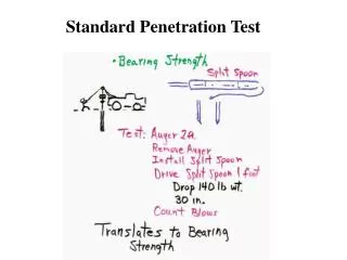
Sample preparation TC-29Workshop on Current Practices of the Use of Bender Element Technique nozzle constant drop-height - Specimens which will have Dr = 50, 80 % as determined at initial stress condition (sv‘ = 25 kPa) are prepared by the air-pluviation method; air-dried sand is poured from a copper nozzle with a rectangular inner cross-section of 1.5 mm×15.0 mm, while maintaining a constant drop-height throughout the preparation. - The final top surface of specimen is made level and smooth by scraping with a thin plate having a straight edge. - These nozzles will be produced by the Japanese domestic committee of TC-29, and will be distributed to the each laboratory.
Specimen set-up (except for consolidometer) TC-29Workshop on Current Practices of the Use of Bender Element Technique -10kPa -25kPa 0 kPa 25kPa - Before the mold is disassembled, a partial vacuum of 10 kPa is applied to the specimen, while the loading piston is unclamped. - Subsequently, the mold is dismantled, and then the vacuum is raised to 25 kPa while ensuring that the specimen can deform freely both in the axial and lateral directions. - Then, initial specimen height and diameter are measured, and the results are reported. -10kPa -25kPa - The partial vacuum is replaced with a cell pressure of 25 kPa while keeping the effective stress constant throughout the procedure.
Consolidation and Measurements of VS TC-29Workshop on Current Practices of the Use of Bender Element Technique - Sample conditions in testing are dry or fully saturated. - In the case of saturated specimen, the specimen is saturated using any of or a combination of appropriate saturation techniques. A back pressure of 100 kPa is applied. - Consolidation condition is isotropic or anisotropic [K=0.5 or K0 (consolidometer)], and the consolidation stresses are sv' = 50, 100, 200 and 400 kPa (see Fig.1). e.g.; in the case of K = 0.5, sv‘ = 50, 100, 200, 400 kPa (sh‘ = 25, 50, 100, 200 kPa).
Isotropic consolidation (1) TC-29Workshop on Current Practices of the Use of Bender Element Technique a) Keeping the isotropic stress state in the drained condition, increase the confining stress to the next isotropic stress state (sc' = 50, 100, 200 or 400 kPa) in one or two minutes as shown in Figure. 400 Isotropic consolidation sv’ = sh’ b) Consolidate 10 minutes on each stress state (open circle marks in Fig.1). c) Measure the changes in the height and volume of the specimen. d) Measure the shear wave velocities using the bender element. 300 Effective Vertical Stress, sv’ (kPa) 200 100 0 0 100 200 300 400 Effective Horizontal Stress, sh’ (kPa)
Isotropic consolidation (2) TC-29Workshop on Current Practices of the Use of Bender Element Technique e) Measure the secant stiffness from stress-strain curve at small strains (less than 0.001%) by applying monotonic or cyclic loading in the drained and/or undrained conditions when possible. f) Measure the changes in the height and volume of the specimen after the measurement of Vs and/or stiffness. 400 Isotropic consolidation sv’ = sh’ 300 Effective Vertical Stress, sv’ (kPa) 200 g) Repeat the processes a) to f) until the final stress state (sc' = 400 kPa) is reached. 100 0 0 100 200 300 400 Effective Horizontal Stress, sh’ (kPa)
Anisotropic consolidation (K=0.5) (1) TC-29Workshop on Current Practices of the Use of Bender Element Technique a) In the drained condition, apply the vertical stress up to50 kPa (sh'=25 kPa and K=0.5). b) Consolidate 10 minutes on K = 0.5 stress state (blue solid circle marks in Fig.). c) Measure the changes in the height and volume of the specimen. d) Measure the shear wave velocities using the bender element. Anisotropic consolidation (K=0.5) 400 300 Effective Vertical Stress, sv’ (kPa) 200 e) Measure the secant stiffness from stress-strain curve at small strains (less than 0.001%) by applying monotonic and/or cyclic loading in the drained and/or undrained conditions when possible. 100 0 0 100 200 300 400 Effective Horizontal Stress, sh’ (kPa)
Anisotropic consolidation (K=0.5) (2) TC-29Workshop on Current Practices of the Use of Bender Element Technique Dsv'=50kPa Dsh'=25kPa f) Measure the changes in the height and volume of the specimen after the measurement of Vs and/or stiffness. g) Increase the horizontal and vertical stresses step by step until next anisotropic stress state (solid circle marks in Fig.1) in one or two minutes on each step. The increment of horizontal and vertical stresses, Dsh', Dsv' are 25 and 50 kPa, respectively. h) Repeat the processes b) to g) until the final stress state (sv'= 400kPa and sh'= 200 kPa) is reached. Anisotropic consolidation (K=0.5) 400 300 Effective Vertical Stress, sv’ (kPa) 200 100 0 0 100 200 300 400 Effective Horizontal Stress, sh’ (kPa)
K0 consolidation(consolidometer) TC-29Workshop on Current Practices of the Use of Bender Element Technique sv'=50, 100, 200 or 400 kPa DH a) In the drained condition, increase the vertical stress to the next stress state (sv' = 50, 100, 200 or 400 kPa) in one or two minutes. b) Consolidate 10 minutes on each stress state. c) Measure the changes in the height of the specimen. d) Measure the shear wave velocities using the bender element. e) Repeat the processes a) to d) until the final stress state (sv' = 400 kPa) is reached.
Report (1) TC-29Workshop on Current Practices of the Use of Bender Element Technique 1) Outline of the test apparatus used (triaxial, torsional, consolidometer apparatus, etc.). 2) Details of benders employed (e.g., maker, shape, dimension, thickness and material of Piezoelectric Ceramics, mounting, the tip-to-tip distance, electrical connections (series or parallel), etc.). Schematic figure indicated dimension of cap and/or pedestal with bender elements.
Report (2) TC-29Workshop on Current Practices of the Use of Bender Element Technique 3) Fill up the items listed in Form attached. (e.g., Lab name, condition of specimen at initial and after consolidation, results of BE test, etc.)
Report (3) TC-29Workshop on Current Practices of the Use of Bender Element Technique E Deviator Stress, sd Axial Strain, ea 4) Input and received wave record in digital data or hardcopy of screen. Sampling frequency and whether filter used or not. 5) Determination of arrival time (Vs), special treatment (cross correlation, self monitoring, etc). 6) Strain rate of monotonic loading, and/or frequency and number of loading cycle of cyclic loading. 7) Stress and strain records on monotonic and/or cyclic loadings in digital data. 8) Any deviations from the procedure outlined in this specification.
Schedule TC-29Workshop on Current Practices of the Use of Bender Element Technique Sept 2003: finalize the spec. in IS-Lyon03, call for participation. Oct 2003: distribution of Toyoura sand to participating organizations. March 2004: report of test results. Contact : TC-29 Website on JGS(http://www.jiban.or.jp/e/tc29/index) or Dr. Satoshi Yamashita yamast@mail.kitami-it.ac.jp (Japanese Domestic Committee member for TC-29) or Dr. Satoru Shibuya shibuya@eng.hokudai.ac.jp (Secretary of TC-29)