Download
1 / 44
730 likes | 2.73k Vues
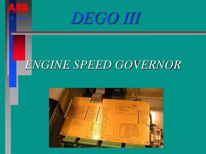
DEGO III. Q-TAGG. ENGINE SPEED GOVERNOR . Space for picture. DEGO III - Main features. Very simple commissioning Cost effective The properties of DEGO II are retained Sturdy electric actuator = low maintenance Fuzzy control Diagnostics functions integrated

E N D
DEGO III Q-TAGG ENGINE SPEED GOVERNOR Space for picture
DEGO III - Main features • Very simple commissioning • Cost effective • The properties of DEGO II are retained • Sturdy electric actuator = low maintenance • Fuzzy control • Diagnostics functions integrated • Built-in instruction (user’s manual)
More features • Customized from a normal PC in Windows format • Inter-active commissioning via the PC • Protocol on all settings can be printed out after commissioning • The governor set-up is easily tested against a realistic simulator program before engine start up
Propulsion governor features • The control algorithm is automatically adopted to the actual running condition • Back-up control bypassing the governor in fixed propeller applications • Excellent load sharing in multi-engine applications • The parameters for most slow speed engines are stored in the programming aid
Generator governor- features • Three modes of operation: • - Speed droop • - Isochronous • - Load control • Program for smooth start-up • Synchronizing integrated • Power measurement integrated
Low Frequency Torsional Oscillations If the shaft system has a resonance that is in a frequency range that the governor can respond to, the governor can amplify the torsional oscillation A misfiring can excite the torsional oscillation In severe cases the torque is changing sign also at load (gives gear hammering) The governor gain setting for stability is extremely low Installation of one pickup on each side of the elastic coupling may be efficient If a Multi Channel Tacho (MCT) is installed, we can guarantee that the governor not is making the situation worse '
Suppression of torsional oscil-lations with the MCT funtion Governorelectronics with Multi Channel Tacho functions F A SPEED U V E F R U ALTERNATOR OR GEARBOX ELASTIC COUPLING
Arrangement for Diesel-Electric propulsion NOT ABB SUPPLY SUPERIOR C/R MSB PANEL CONTROL PANEL GOVERNOR CUBICLE TERMINALS QHFD 552 POWER AMPLIFIER CONTROLLER SPEED TRIMMER FUEL SET TERMINALS UNIT SUPPLY 24 VDC INTERCONNECTION ACTUATOR 48 VDC 24 VDC BATT. HARMONICS FILTER 3x400 VAC TERMINALS SUPPLY UNIT MSB TRANSFORMERS CIRCUIT VT PICKUPS BREAKER CT GENERATOR DIESEL ENGINE
Features in Speed Droop mode Same characteristics as for hydraulic governors The frequency is load dependant (static) and fluctuating with load variations (no feed forward) Difficult to maintain load sharing at loss of load Loading up and loading down is manual Utilised to arrange smooth load up and load down No signals from the switchboard are required
Features in Isochronous mode The frequency is always nominal (50 Hz) Equal load sharing also at low load The load sharing and the frequency is maintained also at large load changes The load sharing is based on electric power Used when the station busbar is isolated The frequency is independent from load variations
Load rejection Without feed forward Withfeed forward
Features in Load Control mode The governor is converted to a "power regulator" The load is independent from frequency variations The desired power level is easily preset The fuel rack is completely steady Requires minimum one unit connected to the busbar in frequency control (electric interlock needed) Utilised to arrange smooth load up and load down
Loading up/down sequence FIX LEVEL AVERAGE LOAD BREAKING POINTS START LEVEL LOAD CONTROL CIRCUIT BREAKER ORDER UNLOAD BREAKER TRIP
Choose the right pick-up location Correct pick-up location Shaft bearing Engine Correct pick-up location This location gives problems Tank top