Download
1 / 48
510 likes | 1.16k Vues
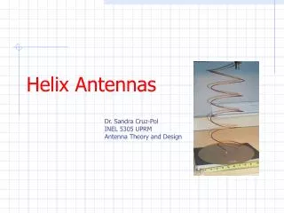
REAL WORLD COMPARISON MEASUREMENTS Clare - VE3NPC QCWA Dinner Nov. 21, 2006. HELIX ANTENNAS. Early Helix – 2 x 10 Turns. 1989. 2 x 15 Turn 70 cm Helix . 1991 ?. AO-13 Antennas. About 1994. AO-40 Antennas. 2001. 13 and 23 cm Helix Arrays. 2003 .

E N D
REAL WORLD COMPARISON MEASUREMENTS Clare - VE3NPC QCWA Dinner Nov. 21, 2006 HELIX ANTENNAS
2 x 15 Turn 70 cm Helix 1991 ?
AO-13 Antennas About 1994
AO-40 Antennas 2001
So How Did We Do? • Only worked AO-40 in mode L/S • 6 other low orbiters were used by others • Used Yaesu FT-736R with 10 watts on L • There were 30 submissions • We made 102 QSO’s, nearly all on SSB • Placed 7th.
VE3NPC L/S QSO’s AO-40 • AO-40 on mode L/S from 16 Sept 01 to 28 Jan 04 • 10 watts output into 4 x 27 T helix array on the L uplink • Works out to about 1500 watts ERP • In that time I logged 832 QSO’s in mode L/S
More Helix Antenna Operation • First satellite QSO in 1988 • Now 18 years later have over 11 K Satellite QSO’s in log • With exception of mode A and K used in early RS satellites all were made using home brew helix ants for 70cm up and down links and 23 cm uplinks
So What ! • I have learned a lot about building and operating helix antennas. • They have worked very well on the air in competition with commercial crossed yagis, loop yagis and dishes that most satellite operators were and are using. • What my paper is about is that according to some published antenna modeling theory they should not have worked as well as the have.
THE HELIX ANTENNA • Invented by Dr. John D Kraus in 1947 • He constructed large arrays of helix antennas for radio astronomy
“the dimensions of the helix are so non-critical that the helical beam antenna is one of the simplest types of antenna it is possible to make” • circumference • turn spacing (phase angle) • reflector size • conductor diameter • helix support (boom)
Kraus • Gain (db)=10log3.325n • Linear function • Double n (turns) - double gain – 3 db • Four times n – four times gain – 6 db
Kraus • Satellite Experimenters Handbook 0.8 > C > 1.2 C = circumference in wavelengths 12 < a > 14 a = pitch angle in degrees But used C = 1 wavelength and a =12.5 degrees
V E3NPC • C = 1 wavelength • pa = 12.5 degrees
Helix Antenna Computer Modeling (NEC) • 1990 ARRL UHF/Microwave Experiments Manual – Bob Atkins KA1GT • 1995 ARRL Antenna Compendium - Emerson • 2005 Proceedings of the Southeastern VHF Society – Cebik W4RNL
NEC Design Theory The NEC designs concluded that : - for a given number of turns there was a particular value of circumference and pitch angle that would provide peak gain. - as the number of turns was increased the increase in gain soon leveled off.
Consequences • NEC modeling peak gain designs used in ARRL publications • Web page helix antenna calculators use NEC peak gain design formula • AMSAT “experts” come up with peak gain formula dimensions
VE3NPC 1990 or so • Constructed several 70cm helix antennas following Bob Atkins design in the ARRL UHF/Microwave Experimenters Manual • They did not give any better performance. • Narrower band width and harder to get good feed match
VE3NPC – 1992/93 • Constructed several different 2.4 GHz helix antennas and arrays for AO-13 mode S • All were over 30 turns and most used Bob Atkins peak gain design • Didn’t work – never even heard beacon • Made 4 ft dish – worked like a charm
Summer 2005 • Dave VE3KL proposed constructing a 70cm helix antenna using the Emerson design • From my previous experience I questioned his choice • Dave was skeptical. • Well that started the ball rolling • Maybe I was wrong but I didn’t think so • Simple matter to compare his with mine • What appeared to be simple turned into a major project • Constructed and compared 10 different helix antenna
Objectives • 1 To compare the peak gain design verses the simple Kraus design. • 2 To test the validity of the difference in gain relative to the number of turns (length in wavelengths). • 3 To test the effects of different boom materials.
Comparison Results Between Four Kraus Design Helix Antennas of Increasing length. C = 1 w/l P.A.= 12.5 deg.
Gain & Directivity • An antenna may be very directive i.e. exhibit a narrow forward beam width but due to the configuration of the side lobes and/or degree of losses, provide higher or lower forward gain
Kraus 12.5 cm-Increased Turns 12 turns 6.5 turns 26 turns 52 turns
70 cm 10 Turn Kraus/Emerson Kraus 10 turns Emerson 10 turns
12.5 cm 2.88 w/l Kraus/Emerson Emerson 12 turns Kraus 13 turns
12.5 cm 5.75 w/l Kraus/Emerson Kraus 26 turns Emerson 24 turns
Conclusions • Casts serious doubt on NEC computer modeling of helix antennas • Ant based on modeling doesn’t give predicted peak gain • 30 Turn helix ants can be made that will give real gain. Useful gain with 52 turns. • Aluminum or PVC OK for boom
Other Verification • Can find no other information on direct experimental evidence to verify the computer modeling results of helical antennas !
VE3NPC 23cm Array Constructed by KB9UPS VE3NPC KB9UPS
WHO CARES !! • Checked my satellite QSL cards • 40 % did not list type of ant • Of the 1267 cards listing type of antenna only 37 used a helix (3%) • Only 3 were in the US • One VK,FY and FP • The rest European (G3RUH pattern?) • 22 countries
G3RUH – James Miller • 1993 published design for 16 turn 2401 MHz helix • C = 1.06 wavelengths • P.A. 12.5 degrees • 3.3 mm copper wire conductor • Boom 1 x 1 inch aluminum • Measured gain (sun noise) = 15.2 dbic • Kraus gain = 17.3 dbic
Central States VHF Society Antenna Range Tests 1995-2006 • 15 helix antennas for 70cm, 33cm,23cm and 13cm measured • 2 met the theoretical (VE3KSK) – G3RUH design • 5 within 1 – 3 db • 8 within 4 – 11 db • Where theoretical = Kraus gain minus 3 db
Southeastern VHF Society Antenna Range Tests 2006 • 2 helix antennas tested at 2304 MHz • One 27 turn and one 16 turn. • Both about 1 db less than Kraus gain minus 3 db
AO-40 Orbit 60 k kilometers