Download
1 / 26
260 likes | 369 Vues
We are the premier manufacturer of Hydraulic Components like Hydraulic Powerpack, Hydraulic Drives and Motors.

E N D
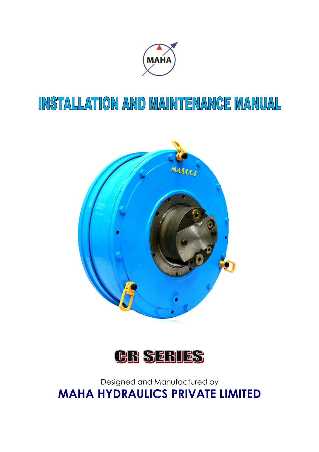
Designed and Manufactured by MAHA HYDRAULICS PRIVATE LIMITED MAHA HYDRAULICS PRIVATE LIMITED MAHA HYDRAULICS PRIVATE LIMITED Designed and Manufactured by
Contents 1. General ……………………………………………………..... 1 Introduction………………………………………………………….. 1 Safety Instructions.. ……………………………..…………………... 2 Functional Description ……………………………………….……... 3 Identifying the Motor………………………………………………… 3 Features………………………………………………………………..4 Technical Data sheet…………………………………………………..5 1.1 1.2 1.3 1.4 1.5 1.6 2. 2.1 2.2 2.3 2.4 2.5 2.6 3. 3.1 Lifting Methods ……………………….….…………………….......... 12 4. Installation ……………………………………………….….…14 4.1 Mounting Instructions …………………….………………….............14 4.2 Oil Connections....................................................................................14 4.3 Start-up Procedure ……………………….......…………..………....15 4.4 Flushing ……………………………………..…………………......... 16 5. Maintenance……………………………………………..……....17 5.1 Hydraulic System periodic Maintenance …………………….. 17 5.2 Motor Maintenance …………………………………………… 18 Technical Information ……………………………….……..…6 Motor Data ………………………………………………………….. 6 Recommended Charge pressure …………………………………….. 6 Hydraulic Fluid ………………………………………………........... 6 Estimated Life...................................................................................... 8 Calculation Fundamental ……………………………………………..10 Chart diagrams………………………………………………………...11 Safety for Handling…………………………………………… 12 6. Storage of Hydraulic Components …………………………. 19
7. Trouble Shooting........................................................................20 7.1 Causes and remedies..................................................................... 20
Preface . Mascot CR Series Hydraulic motor are reliable for Heavy duty high torque low speed applications. These hydraulic motors are mostly working in mines and steel sectors, where continuous duty cycle with high efficiency on varying load conditions is demanded. This manual provides the necessary information for installation and maintenance of hydraulic motors, however the development hydraulic motor is a continuous process as we therefore reserve the right to introduce amendments in the manual as we deem necessary without notice and obligation.
1.0 GENERAL: 1.1 INTRODUCTION The Hydraulic Motor CR Series is designed and manufactured considering the provisions of directives, standards and specifications relating to this technology. There is however still a risk of personal injury or damage to property if the following safety instructions and warnings contained in this document are not observed. ?User should read these instructions completely and thoroughly before working with the hydraulic power unit/hydraulic drive assembly, using our mascot hydraulic motors. ?When reading these instructions, user should always have the product-specified documentation on hand. ?These instructions, together with the relevant product-specified documentation, should be kept so as to be readily accessible to all users. Always include the operating instructions and the product specified documentation when passing the hydraulic power unit/hydraulic assembly/Hydraulic Motor to a third party. Due to the interaction between the hydraulic power unit/Hydraulic Motor and the complete machine, the installation of the hydraulic power unit into the machinery will result in additional potential hazards. This applies in particular to the influence of hydraulic and electric controls on hydraulic drives generating mechanical movements. It is therefore essential for the manufacturer of the complete machine to have undertaken an independent risk assessment. Furthermore, the manufacturer must on this basis have prepared operating instructions for the complete machine. These operating instructions are not substitute for the operating instructions of the complete machine. 1
1.2 SAFETY INSTRUCTIONS. In this catalogue the following signs which can or will cause personal injury or substantial property damage. Depending on the probability of the hazard, and how serious the injury or property damage could be, there are three levels of classification. INSTRUCTIONS. the following signs will find, which indicate a potential hazard, which can or will cause personal injury or substantial property damage. Depending on the probability of the hazard, and how serious the injury or property damage could be, there are three levels of classification. which indicate a potential hazard, which can or will cause personal injury or substantial property damage. Depending on the probability of the hazard, and how serious the injury or property damage could be, DANGER severe personal injury, death, or substantial property damage if the warning is ignored. WARNING cause severe damage CAUTION Will Or can cause minor personal injury or property damage if the warning is ignored. DANGER is used to indicate the presence of a hazard which will cause severe personal injury, death, or substantial property damage if the warning is ignored. is used to indicate the presence of a hazard which will cause severe personal injury, death, or substantial property damage if the DANGER WARNING is used to indicate the presence of a hazard which can cause severe personal injury, Hazards or substantial property damage if the warning is ignored. is used to indicate the presence of a hazard which can rds or substantial property WARNING CAUTION is used to indicate the presence of a hazard which Or can cause minor personal injury or property damage if warning is ignored. is used to indicate the presence of a hazard which Or can cause minor personal injury or property damage if CAUTION Instructions carefully before attempting to assemble, install, operate, or maintain these products. Failure to comply with these instructions may result in Personal injury and/or may result in property damage. Retain these instructions for future reference. Read General Safety Instructions operate, or maintain these products result in Personal injury and/or may result in property damage. Retain these instructions for future reference. GENERAL. •Check the hydraulic motor you received at site is the correct purchase order, Check the model code of motor and identify the name plate details to verify. •Ensure the hydraulic motor ports are sealed and all the lifting hooks position for lifting. Read instructions for removing the motor from the packing. •Service and repair of the electrical, hydraulic and the mechanical functions, as well as controls and settings require professional service proper knowledge should not attempt to undergo any work. •Safety equipments are during mounting and maintenance provided in accordance with the regulations prevailing in the local country provided in accordance with the regulations prevailing in the local country provided in accordance with the regulations prevailing in the local country. carefully before attempting to assemble, install, Failure to comply with these instructions may result in Personal injury and/or may result in property damage. Retain these Check the hydraulic motor you received at site is the correct Check the model code of motor and identify the name plate Check the model code of motor and identify the name plate Check the hydraulic motor you received at site is the correct one as per your Ensure the hydraulic motor ports are sealed and all the lifting hooks are in Ensure the hydraulic motor ports are sealed and all the lifting hooks position for lifting. Read instructions for removing the motor from the packing. position for lifting. Read instructions for removing the motor from the packing. repair of the electrical, hydraulic and the mechanical functions, as well as controls and settings require professional service. Personnel proper knowledge should not attempt to undergo any work. repair of the electrical, hydraulic and the mechanical functions, as Personnel without s are necessary for the prevention of accidents ounting and maintenance of motors. Safety precautions should be of accidents to ensure Safety precautions should be 2
1.3 FUNCTIONAL DESCRIPTION. Mascot CR Series Hydraulic motor are radial piston type with rotating case . The case is mounted on stationary cylinder block by two main bearings. An even number of radially positioned pistons work in cylinder bores in the cylinder block, which also houses the inlet and outlet ports. Each piston is working against a roller beam. The cam ring anchored to the rotating case. The distributor directs the input oil to the pistons during the works strokes and returns the exhausted oil back to the tank. The distributor is coupled to the rotating case through safety fasteners. 1.4 IDENTIFYING THE MOTOR. A metal plate is located on the motor Rear end housing where you can find the complete code that describes the configuration of the motor , i.e, Motor Type , Displacement , Serial No , Weight , and Max pressure are indicated . Name Plate with complete Model code 3
NAME PLATE DETAILS: 1.Type 2.Displacement 3.Serial No 4.Weight 5.Max.Pressure : : : : : Model code given below . Displacement of the motor. Year, month and our sequence number. Weight of the motor. Max.Allowable operating pressure of the motor. 1.5 FEATURES High torques Our CR Motor series is high torque low speed motor ,which can be mounted directly on shaft without intermediate gears. This provides many practical benefits which appeal to the users of the equipment. Variable speed control CR Motor can drive in both directions with variable speed by smoothly controlling the flow of oil in the circuit. High efficiency The mechanical efficiency as well as the starting efficiency is 97% . Because of the extremely low moment of interia the motor is virtually insensitive to shock loads,and protects the driven equipment. Low speeds Smooth , low speed performance from zero to rated speed without the need of reduction gears and no compromise on output torque. 4
2.0 TECHNICAL INFORMATION. 2.1 MOTOR DATA: Specification Motor Frame Size Speed Rated Speed Max Max pressure Displacement Torque Per rev Metric litres Cu.in Ft.lb / 100psi Nm/bar rpm rpm bar psi CR6.7 6.8 418 108 108 95 175 350 5000 2.2 RECOMMENDED CHARGE PRESSURE The motor must be connected to the hydraulic system so that it receives sufficient charge pressure at the low pressure connection. This applies to all types of installations. Max case pressure is 3Bar / 43.5 psi The Max permitted case pressure at stand still is 8Bar/11psi 2.3 HYDRAULIC FLUID. The Mascot hydraulic motors are primarily designed to operate on conventional petroleum based hydraulic oils. The hydraulic oil can be chosen in consultation with the oil supplier of your local sales office, bearing the following requirements in mind. General: The oil shall have FZG (90) fail stage minimum 11 described in IP 334 (DIN 51354).The oil must also contain inhibitors to prevent oxidation, corrosion and foaming. The viscosity of mineral oil is highly dependent of the temperature. The final choice of oil must depend on the operating temperature that can be expected or that has been established in the system and not in the hydraulic tank. High temperatures in the system greatly reduce the service life of oil and rubber seals, as well as resulting in low viscosity, which in turn provides poor lubrication. Recommended Viscosity at Operating Temperature: 40 -150 cSt/187-720SSU 6
Viscosity limits. Viscosity index = 100 recommended = 150* for operation with large temperature difference. Min. permitted in continuous duty Min. permitted in intermitted duty Max. permitted 40 cSt/187 SSU 20 cSt/98 SSU 10000 cSt/48000 SSU Temperature limits Normal operating temperature should be less than +50°c (122°F) Nitrile seals ( std motor) -35°c til +70°c, -20°c til +100°c Nitrile seals ( std motor) -31°F til + 158°F , -4°F til +212°F ?Fluid Filtration: To ensure a smooth and reliable motor operation, the fluid must comply with to one of the following filtration classes, 1.Class 9 according to NAS 1638 2.Class 6 according to SAE,ASTM 3.Class 20/17/16 according to ISO 4406:1999 To ensure a long motor life time class 8 according to NAS 1638 is recommended Filtering recommendations: Before start-up, check that the system is thoroughly cleaned. In general the contamination level in our motors should not exceed ISO 4406 19/15 (NAS 10). For heavy-duty industrial applications the contamination level should not exceed ISO4406 16/13 (NAS 7). When filling the tank and motor case, we recommend the use of a filter with the grade of filtration β10=75. 7
Explanation of "Grade of filtration": Grade of filtration β10=75 indicates the following β1 0 means the size of particle >10|a,m that will be removed by filtration. =75 mean the grade of filtration of above mentioned size of particle. The grade of filtration is defined as number of particles in the oil before filtration in relation to number of particles in the oil after filtration. Once the oil contains number of particles >10 µm This means that number of particles have been filtered (98.6% ) Mixing different oils, Mixing oils of different brand or different oils of the same brand may lead to the formation of sediment and sludge, consequently a rapid, irreversible deterioration of the system is induced. 2.4 ESTIMATE LIFE The estimated life of hydraulic motor can be calculated using the formula given below. The life calculated from the formula is an L.o life. By definition, 90% of motors should exceed the L.o life, assuming proper installation, maintenance and operation. The life calculation is applicable for normal torque drive installations and to systems where radial shaft loads are not excessive where high axial and radial shaft loads are present, Life Formula LOP = Lr * (Pr)33 * Sr Fop Where Lop= Estimated Llo operating life (hours) Lr= Expected life at rated pressure and hours (see table) Pr = Rated Pressure (see table) Sr= Rated speed (RPM) (see table) Fop= Operating factor determined from operating pressure and speed To determine Fop 8
a) When speed and pressure are constant: Fop= (Pop)3.3*Sop Where Pop = Operating inlet pressure (charge pressure + delta pressure) Sop = Operating Speed (RPM) b) When speed is variable and pressure is constant: Fop= (Pop)3.3*Swp Where Srt= Time weighted average speed (RPM = T1S1+T2S2+…….+TnSn Where T1 ,T2 ,…….,Tnequals the fraction of time during which S1 ,S2 ,…….,Sn occur; i.e, Σ T1 ,T2 ,…….,Tn=1 and Tn= tn tt Where tnis the actual time during which Sn occurs, ttis the total time of loading. c) When speed is constant and pressure is variable: Fop= (Pwt)3.3*Sop Where Pwt = Time weighted nonlinearly averaged pressure = [T1(P1)3.3 +T2 (P2)3.3+…….+Tn (Pn)3.3]0.3 Where T1 ,T2 ,…….,Tnequals the fraction of time during which P1 ,P2 ,…….,Pn occure d) When both speed and pressure are variable: Fop= Fwt Where Fwt = Time weighted nonlinearly averaged operating factor = T1(P1)3.3S1 +T2 (P2)3.3S2+…….+Tn (Pn)3.3Sn Where T1 ,T2 ,…….,Tnequals the fraction of time during which P1 at S1, P2 at S2,……,. Pn at Sn occur. 9
2.5 CALCULATION FUNDAMENTALS 2.5 CALCULATION FUNDAMENTALS 10
2.6 – CHART DIAGRAMS FOR CR DIAGRAMS FOR CR-MOTOR. Overall efficiency, 40cSt / 187 SSU Pc=12bar ( 174 psi) verall efficiency, 40cSt / 187 SSU Pc=12bar ( 174 psi) Volumetric loss – 40Cst/187 SSU 40Cst/187 SSU The diagrams above shows the average values. When calculating volumetric losses using other viscosities, multiply the value given using other viscosities, multiply the value given in the diagram by the factor K. The diagrams above shows the average values. When calculating volumetric losses The diagrams above shows the average values. When calculating volumetric losses in the diagram by the factor K. 11
3.SAFETY FOR HANDLING •Observe the transport instructions, e.g on the packing •The package can be opened for inspection purposes, package .It should not be removed before assembling the unit. 3.1 – LIFTING METHODS One of the methods shown here must be used when handling the SAFETY FOR HANDLING the transport instructions, e.g on the packing The package can be opened for inspection purposes, however re package .It should not be removed before assembling the unit. package .It should not be removed before assembling the unit. however re-seal the LIFTING METHODS One of the methods shown here must be used when handling the motor. motor. DANGER Before lifting, check the lifting eyes are screwed tools can handle the weight tools can handle the weight the lifting eyes are screwed fully make sure fully make sure that the lifting Lifting Hook Capacity Lifting Hook Capacity – 5Tonnes 12
CAUTION Always make sure where the centre of gravity is before any lifting .Never stand below a hanging motor. Standing the motor on flat surface, when the motor is placed on a flat surface such as floor it must stand either on its outer diameter or on the suitably protected end face of the hollow shaft. Note : When in storage the motors must always be placed on the end face to the hollow shaft. It is also advisable to provide supports at the mounting surface of the motor. 13
4.0 INSTALLATION : 4.1 MOUNTING INSTRUCTIONS INSTRUCTIONS . To ensure the motor work properly it must be possible precision. Every item connected to the motor that does requirements of the following instructions may result in stresses that ad affect the basic rating life of the affect the basic rating life of the motor. work properly it must be installed with the greatest Every item connected to the motor that does requirements of the following instructions may result in stresses that ad requirements of the following instructions may result in stresses that adversely installed with the greatest Every item connected to the motor that does not meet the The motor is normally filled with oil up to the shaft centre. If the oil tank is positioned above the shaft centre, the oil level will raise a corresponding amount positioned above the shaft centre, the oil level will raise a corresponding amount positioned above the shaft centre, the oil level will raise a corresponding amount The motor is normally filled with oil up to the shaft centre. If the oil tank is The motor is normally filled with oil up to the shaft centre. If the oil tank is It is recommended that drainage is arranged so that the motor is completely filled oil. The motor must always be connected so that sufficient charge pressure is obtained at the low pressure connection. This is especially important at high speed and with rapid reversing. the drain port “D” must be connected directly to speed and with rapid reversing. the drain port “D” must be connected directly to It is recommended that drainage is arranged so that the motor is completely filled with oil. The motor must always be connected so that sufficient charge pressure is obtained at the low pressure connection. This is especially important at high speed and with rapid reversing. the drain port “D” must be connected directly to the tank in order to avoid exceeding the maximum permitted case pressure. o avoid exceeding the maximum permitted case pressure. o avoid exceeding the maximum permitted case pressure. It is recommended that drainage is arranged so that the motor is completely filled oil. The motor must always be connected so that sufficient charge pressure is obtained at the low pressure connection. This is especially important at high 4.2 OIL CONNECTIONS OIL CONNECTIONS “A” – PORT Main connection : BSP 1 PORT Main connection : BSP 1-1/4” “B” – PORT Main Connection : BSP 1 PORT Main Connection : BSP 1-1/4” D1 – Drain Connection : BSP 3/4” Drain Connection : BSP 3/4” D2 – Drain connection : BSP 3/4” Drain connection : BSP 3/4” 14
4.3-START UP PROCEDURE. 1.Fix the torque arm ( if required ) 2.Fill the motor casing with oil till the maximum level reached 3.Connect and tighten all necessary fittings and hoses, 4.Check the rotational directionof the electric motor by switch on and off the control. 5.Permantely switch on the electric motor and note charge pressure. 6.Give the displacement command to the hydraulic pump and watch the rotation of the hydraulic motor ( This will be carried out in No load condition) 7.After attaining the stated RPM nad safe pressure limits,then proceed for the load condition. 4.4 FLUSHING To avoid high temperature in the motor case , the heat must be cooled away because high temperature gives lower viscosity and that gives reduction in service life. Low viscosity also gives reduced permitted output power from the motor. For continuous Duty in applications with an ambient temperature of +20°C ,The motor case must be flushed when the output power exceeds . Max power without flushing - 120Kw , WARNING When the motor is provided with flushing oil, please ensure motor case pressure does not exceed the allowable limit 15
5.0 MAINTENANACE: The scope of this section is to indicate the necessary operations for a correct maintenance of the motor to grant long lasting performances and reliability. The information of this section is intended for all qualified technical personnel assigned to the maintenance of the machine. A visual inspection is to be undertaken to detect obvious faults: ?Incomprehensible notes or warning signs. ?Leaks ?Loose and/or missing components ?Indication of the application of external force. 5.1 HYDRAULIC SYSTEM PERIODIC MAINTENANCE Verify the possible cause of leakage in the complete hydraulic system; in case leakage is present •Tighten the fixing screws by means of a wrench, specially if high or frequent change of direction of application of the load characterize the application •Replace failed or exhausted seals. Inspect and keep clean all system’s filters (air, oil and magnetic). •Replace the dirty filters •Inspect the tank and check the possible presence of water or humidity. During system’s function, it is necessary to verify that pressure and temperature of the operating fluid are those initially determined. •Check the characteristics of the used hydraulic fluid. •Check that the hydraulic system does not get contaminated by external agents. 16
5.2 MOTOR MAINTENANCE. In order to keep the motor in perfect efficiency condition, it is necessary to observe a minimum maintenance activity as described in the chapters here below. Filters Cleaning Process The system filters must be changed after the first 200 working hours. The subsequent filters’ replacement or cleaning has to be performed every 3 months or 500 operating hours, whatever one is the first to occur (in case a filter cleanliness level indicator is present, as soon as the signal of locking is received). Operating Fluid Change The oil loses its viscosity after a certain amount of time, which reduces the lubrication effect .High temperature and pressure always reduces the life length of the oil. •After 6 months or 4000 running hours (whichever comes first) the oil should be analysed. •Clean the hydraulic oil tank every year. •Change oil as soon as its necessary. •Check that the tank is clean each time you change oil. Degree of contamination A high degree of contamination of the operating oil causes a severe wear of all hydraulic components: for this reason, the cause of the contamination must be identified and eliminated. This analysis might also help in better optimizing the schedules for the oil replacement. In any case, the oil changes have to be performed at least every 12 months. Oxidation Mineral oil gets oxidized proportionally to the usage degree and operating temperature. The oil oxidation gets evident because of its change of colour, bad smell, acidity increase and because of the generation of sludge inside the tank. In case symptoms of this kind are detected, the system oil must be immediately changed. 17
COMMISSIONING During the start up period, a hydraulic installation must be checked regularly and thoroughly at frequent intervals. Working pressure and charge pressure must be checked, and correspond with calculated values. •Pressure in the drain line, measured at the motor, should be less than 3 bar. •Check all lines, connections, flanges, bolts etc. Tighten if necessary. •Check other possible leakage points and replace any faulty parts. •Change dirty hydraulic fluid immediately. •Control that rotating parts cannot cause damage. 6.0. STORAGE OF HYDRAULIC COMPONENTS: Hydraulic Components are expensive and so regardless of the amount of spares that is carried. One thing to make sure of is that inventory is not deteriorating in storage. With this in mind, here are a few points for the effective long-term storage of hydraulic components: •Hydraulic components like pumps, motors, cylinders and valves should be stored indoor in a clean, dry area. •Plug the components port connections with steel (not plastic) plugs or blanking plates. Plastic plugs don’t provide the same sealing integrity as their metal counterparts and are easily dislodged – both of which can result in contaminant ingression. Important : •Clean hydraulic oil to be filled through case drain and Service ports of hydraulic motors. Hydraulic oils to be replaced once in a year if the components stored for longer duration. The motors can be stroed either in vertical direction or horizontal direction make sure all the internal components are fully submerged in oil. 18
7. TROUBLE SHOOTING: 7.1 CAUSES AND REMEDIES. MALFUNCTION POSSIBLE CAUSE SOLUTION The motor Does not run, 1.Mechanical transmission block 1. Check the pressure in the system. pressure has exceeded the setting valve of the safety valve, remove the load from the transmission. If the 2.the motor does not generate enough torque because the working pressure is too low 2.check the pressure level in the system and correct the setting of the pressure limit valve if necessary 3.the motor is not supplying enough power 3.check the hydraulic system The motor turns in wrong direction The hydraulic inlet and return connection A and B are reversed. Correct the connections. The motor does not run smoothly Pressure through put fluctuations in the hydraulic system 1) Distributor still breaking in 2) The boost pressure is too low and / or Look for the cause in the hydraulic system or mechanical transmission The motor is noisy 1) After the first few running hours, the noise (squeaking) generated by the contact surfaces of the distributor disappears. unit 2) Set the boost pressure value as described 19
3) Resonance inside the Pipelines3 3) Optimize the diameter and type of connecting lines on the motor. 4) In no-load operation, you may bearings turn; disappears motor is run under load. 4) Bearings hear the this the when Pressure or flow fluctuations in hydraulic system 1. Oil sweating between motor and components. 2.Shaft seal leakage Motor runs jerkily Find the causes in the system or in the driven unit Clean carefully motor and verify if the leakage is still present. External leakage the Check the Seal, if any damage found, Replace the seal. If the proposed solutions do not solve the malfunction, or in case of doubt or problems not listed in the table. Motor problems are often highlighted by drastic variations in the case flow in terms of the capacity and/or impurities present External oil leaks. 20
Designed & Manufactured by, MAHA HYDRAULICS PRIVATE LIMITED Plot F-62, SIPCOT Industrial Complex, Irungattukottai – 602 105 Sriperumbudur, Kanchipuram Dist.Tamil Nadu, India. Tel: +91-44-47193081/82/83, Fax: +91-44-47193080 Email: sales@mahahydraulics.com Web: www.mahahydraulics.com Copy rights Reserved.