Download
1 / 1
10 likes | 241 Vues
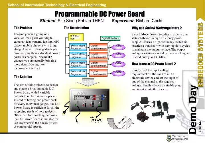
18.5 DC Input. Digital Interface. Switch Mode Regulator. Digital potentiometer. Output. Switch Mode Regulator. Digital potentiometer. Output. Switch Mode Regulator. Digital potentiometer. Output. Switch Mode Regulator. Digital potentiometer. Output. Max Current. Cycling on/off.

E N D
18.5 DC Input Digital Interface Switch Mode Regulator Digital potentiometer Output Switch Mode Regulator Digital potentiometer Output Switch Mode Regulator Digital potentiometer Output Switch Mode Regulator Digital potentiometer Output Max Current Cycling on/off Polarity Voltage + Parameter Select. . A V - Output Select 1 2 3 4 Programmable DC Power Board Student: Sze Siang Fabian THEN Supervisor: Richard Cocks The Construction The Problem Why use Switch Mode regulators ? Imagine yourself going on a vacation. You pack your digital camera, video camera, lap top, MP3 player, mobile phone, etc to bring along. And with these gadgets you have to bring their individual power packs or chargers. Instead of 5 gadgets you are actually bringing more than 10 items, how inconvenient is that? Switch Mode Power Supplies are the current state-of-the-art in high efficiency power supplies. It uses a high frequency switch (in practice a transistor) with varying duty cycles to maintain the output voltage. The output voltage variations caused by the switching are filtered out by an LC filter. How to use a DC Power Board ? Simply read the input voltage requirement off the back of a DC electronic device and set the input of one of the channel to the required voltage. Finally choose a suitable plug and insert it into the device. The Solution The aim of this project is to design and create a Programmable DC Power Board with 4 variable outputs to replace 4 power packs. Instead of having one power pack for every individual gadget, one DC Power Board is sufficient for all the supplying needs of your gadgets. Other than for travelling purposes, the DC Power Board is suitable for use anywhere in the house, offices or commercial spaces. Replace