Download
1 / 44
450 likes | 831 Vues
CPEG 419 Introduction to Networks. [Week 2]. Administrative Issues. Homework #1 assigned. Due in 2 weeks. . Review. Goal: Send a file from a web server (e.g. yahoo.com) to a web client (e.g. your PC). Application e.g. http server. Application e.g. http client. Transport Layer

E N D
CPEG 419Introduction to Networks [Week 2] University of Delaware CPEG 419
Administrative Issues • Homework #1 assigned. • Due in 2 weeks. University of Delaware CPEG 419
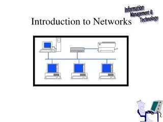
Review Goal: Send a file from a web server (e.g. yahoo.com) to a web client (e.g. your PC). Application e.g. http server Application e.g. http client Transport Layer e.g. TCP source Transport Layer e.g. TCP receiver Network Layer: IP Network Layer: IP Network Layer Network Layer Link Layer e.g., CSMA/CD Link Layer e.g., CSMA/CD Link Layer Link Layer Link Layer Physical Layer e.g., twisted pair Physical Layer e.g., twisted pair Physical Layer Physical Layer Physical Layer University of Delaware CPEG 419
Review University of Delaware CPEG 419
Review • Physical (as opposed to logical) Layer – Sends bits from one point to another. Error correction and media access is not an issue. • To transmit at a 10Mbps we need at least 5MHz. Transmitter Receiver Wire, fiber, wireless? Noisy, how fast, how to encode? University of Delaware CPEG 419
Review: Multi-level Signals Bit Rate and Baud Rate • The number of bits transmitted can be increased by transmitting more than one bit in one time slot • Baud rate: number of times per second signal changes its value (voltage). • Each value might “carry” more than 1 bit. • Example: 8 values of voltage (0..7); each value conveys 3 bits, ie, number of bits = log2V. • Thus, bit rate = log2V * baud rate. • For 2 levels, bit rate = baud rate. University of Delaware CPEG 419
Transmission Impairments • Types of impairments: • Attenuation. • Delay distortion. • Noise. • Multi-path Fading (wireless only). University of Delaware CPEG 419
Attenuation • Weakening of the signal’s power as it propagates through medium. • Function of medium type • Guided medium (wired): logarithmic with distance. • Unguided medium (wireless): more complex (function of distance and atmospheric conditions). University of Delaware CPEG 419
Attenuation • Problems and solutions: • Insufficient signal strength for receiver to distinguish between the signal and noise: use amplifiers/repeaters to boost/regenerate signal. • Attenuation increases with frequency: special amplifiers to amplify high-frequencies (equalization). University of Delaware CPEG 419
Attenuation Let Rf be the received signal power at frequency f Let Tf be the transmitted signal power at frequency f The attenuation in dB is: A signal is sent at –10dBW. The attenuation is 12dB. Transmission (dBW) – Attenuation = -10 dBW – 12 dB = -22 dBW. The received signal has power = University of Delaware CPEG 419
Noise • Noise: undesired signals inserted anywhere in the source/destination path. • Different categories: thermal (white), crosstalk, impulse, etc. noise received signal is an attenuated version of the transmitted signal plus noise. attenuation transmitter + University of Delaware CPEG 419
Thermal Noise • Any conductor and electronic device has noise due to thermal agitation of electrons • The thermal noise found in 1Hz is N = k T (W/Hz) k = 1.3 e –23 (Boltzmann’s constant) T is the temperature in Kelvin N is noise power in watts per 1Hz of bandwidth • Total noise is N = k T B B is total bandwidth Example: 20 degrees C and 1Ghz. N = k (20+273) 109 = 3.8 10-12 in dBW = 10 log(N) = -114 dBW University of Delaware CPEG 419
Transmission Power (dBW) - Gain(dB) = -40 dBW. Suppose that –10 dBW is transmitted on other wires. And the crosstalk gain is 50. Then the noise received has power = Crosstalk • Wires act as antennas. They broadcast energy when the signal switches and receive energy for any other source (e.g., other wires, radios, microwave ovens, the big bang, etc.). • Crosstalk can be reduced by careful shielding and using twisted pairs. • The longer the wires, the more significant the crosstalk. power found on the wire of interest Crosstalk gain per km is power at other wires Suppose that –10 dBW is transmitted on other wires. And the crosstalk gain is 30. Then the noise received has power = Transmission Power (dBW) - Gain(dB) = -60 dBW University of Delaware CPEG 419 better?
Other noises • Coupling through common impedance (power supply noise). This is a major source at the transmitter and receiver. • Galvanic Action. Dissimilar metals and moisture produce a chemical wet cell (battery). • Triboelectric effect from bends in cable. • Shot Noise. Present in semiconductors. • Contact noise. Due to imperfect contacts. • Popcorn noise. Minor defects in junction in a semiconductor, often due to metallic impurities. University of Delaware CPEG 419
Decibel and Signal-to-Noise Ratio • Decibel (dB): measures relative strength of 2 signals. • Example: S1 and S2 with powers P1 and P2. NdB = 10 log10 (P1/P2) • Signal-to-noise ratio (S/N): • Measures signal quality. • S/NdB = 10 log10 (signal power/noise power) University of Delaware CPEG 419
SNR Suppose that we transmit at a very high power, so thermal and other noises are small compared to crosstalk. This depends on the cable. Furthermore, it may not be possible to transmit at such a high power that other noises can be neglected. University of Delaware CPEG 419
0 0 0 1 1 1 1 1 1 0 0 0 1 1 1 0 0 0 1 1 1 1 1 1 0 0 0 0.5 times the bit-rate 0.75 times the bit-rate 0 1 1 0 1 0 1 1 0 1 times the bit-rate SNR=13 2 times the bit-rate University of Delaware CPEG 419
Delay Distortion • Speed of propagation in guided media varies with frequency. • Different frequency components arrive at receiver at different times (more about this later). • Solution: • equalization techniques to equalize distortion for different frequencies. • Use fewer frequencies. University of Delaware CPEG 419
Multi-path reflection (wireless) Because of reflections, a signal may take many paths from transmitter to receiver. transmitter Objects such as buildings, people, etc. receiver Signals that take alternative paths will arrive later. University of Delaware CPEG 419
Multi-path reflection or delay spread (wireless) late arriving signals line of sight signal getting small received signal At 10Mbs, if the difference in paths is 30 meters, then the alternative signals arrive at exactly the next slot. (Use the fact that light travels a 300000000 m/s. University of Delaware CPEG 419
Channel Capacity 1 • Channel Capacity is the rate at which data can be transmitted over communication channel. • We saw earlier that to send a binary data at a rate R, the channel bandwidth must be greater than ½ R. • So, if the bandwidth of the channel is B, it might be possible to transmit at a rate of 2B. University of Delaware CPEG 419
Channel Capacity 2 • For a fixed bandwidth, the data rate can be increased by, increasing number of signal levels. However, the signal recognition at receiver is more complex and more noise-prone. • The data rate becomes • C = 2B log2V, where V is number voltage levels. • Is it possible to continually increase V to make C arbitrarily large? University of Delaware CPEG 419
Channel Capacity 3 • Noisy channel: Shannon’s Theorem • Given channel with B (Hz) bandwidth and S/N signal-to-noise ratio, C (bps) is • C = B log2 (1+S/N) • Theoretical upper bound since assumes white noise (e.g., thermal noise, not impulse noise from crosstalk or multipath reflection ). Suppose that the noise is –30dBW, the signal strength is at –20dBW and the signal is transmitted with 1MHz bandwidth. The channel capacity is 106 log2 (1 + 10(10/10)) = 106 log2 (1+10) = 3.4 106 bps How many signaling levels would be required? data rate = 2B log2 (V) 3.4 106 bps = 2 106 log2(V) V = 3.4 (?) University of Delaware CPEG 419
Transmission Media Chapter 4 • Physically connect transmitter and receiver carrying signals in the form electromagnetic waves. • Types of media: • Guided: waves guided along solid medium such as copper twisted pair, coaxial cable, optical fiber. • Unguided: “wireless” transmission (atmosphere, outer space). University of Delaware CPEG 419
Guided Media: Examples 1 • Twisted Pair: • 2 insulated copper wires arranged in regular spiral. Typically, several of these pairs are bundled into a cable. (What happens if the twist is not regular? Reflection?) • Cheapest and most widely used; limited in distance, bandwidth, and data rate. • Applications: telephone system (from home to local exchange connection). • Unshielded and shielded twisted pair. • What is a differential amplifier? University of Delaware CPEG 419
Guided Media: Examples 1 • Twisted pair – continued • Category 3: Unshielded twisted pair (UTP) up to 16MHz. • Cat 5: UTP to 100 MHz. • Table 4.2. Suppose Cat 5 at 200m (the limit of 100Mbps ethernet is 300m). • The dB attenuation at 100m is 22.0. So at 200m, the attenuation is ???. Suppose we transmit at –80dBW. Then the received signal has energy of ????. • The near-end crosstalk gain is 32dB per 100m. So the crosstalk energy is ???? • The SNR is ????? (neglecting thermal noise). 44 –124dBW –144dBW 20dB University of Delaware CPEG 419
Examples 2 • Coaxial Cable • Hollow outer cylinder conductor surrounding inner wire conductor; dielectric (non-conducting) material in the middle. • Less capacitance than twisted pair, so less loss at high frequencies. Also, Coaxial has more uniform impedance. • Applications: cable TV, long-distance telephone system, LANs. • Repeaters are required every few kilometers at 500MHz. • +’s: Higher data rates and frequencies, better interference and crosstalk immunity. • -’s: Attenuation at high frequency (up to 2 GHz is OK) and thermal noise. University of Delaware CPEG 419
Examples 3 • Optical Fiber • Thin, flexible cable that conducts optical waves. • Applications: long-distance telecommunications, LANs (repeaters every 40km at 370THz!). • +’s: greater capacity, smaller and lighter, lower attenuation, better isolation, • -’s: Not currently installed in subscriber loop. Easier to make use to current cables than install fiber. University of Delaware CPEG 419
Examples 3 – types of fiber lower index of refraction • Step-index multimode shorter path longer path absorbed total internal reflection higher index of refraction Since the signal can take many different paths, the arrival the received signal is smeared. Input Pulse Output Pulse University of Delaware CPEG 419
Examples 3 – types of fiber • Single mode If the fiber core is on the order of a wavelength, then only one mode can pass. Wavelengths are 850nm, 1300nm and 1550nm (visible spectrum is 400-700nm). 1550nm is the best for highest and long distances. Attenuation: -0.2dB/km to -0.8dB/km (if the ocean was made of this glass you could see the floor like you can see the ground from an airplane) University of Delaware CPEG 419
Input Pulse Output Pulse Examples 3 – types of fiber Even for single mode fiber, a pulse gets smeared. Solitons are a particular wave pulse that does not disperse. University of Delaware CPEG 419
Fiber Repeaters : Two Approaches • Convert the signal to analog. Convert to digital and then send a transmit received signal. • Optical repeater. A nonlinear optical amplifier shapes and amplifies the pulse. A single repeater works for all data rates! (more about optical networks later) University of Delaware CPEG 419
Wavelength-division multiplexing (WDM) • Wavelength-division multiplexing • Multiple colors are transmitted. • Each color corresponds to a different channel. • In 1997, Bell Labs had 100 colors each at 10Gbps (1Tbps). • Commercial products have 80 colors at 10Gbps. University of Delaware CPEG 419
Fiber vs. Cable • Fiber is light and flexible. • Fiber has very high bandwidth. • Fiber is difficult to install (I can’t do it). • Fiber interfaces are more expensive than cable. University of Delaware CPEG 419
Wireless Transmission University of Delaware CPEG 419
1022 1016 UV Gamma -ray X-ray Electromagnetic Spectrum Cell phones put out milliwatts. Light bulbs put out 100 watts. University of Delaware CPEG 419
Wireless Transmission • Omni-directional – the signal is transmitted uniformly in all directions. • Directional – the signal is transmitted only in one direction. This is only possible for high frequency signals. University of Delaware CPEG 419
Terrestrial Microwave • Parabolic dish on a tower or top of a building. • Directional. • Line of sight. • With antennas 100m high, they can be 82 km (50 miles). • Use 2 – 40 GHz. • 2 GHz: bandwidth 7MHz, data rate 12 Mbps • 11 GHz: bandwidth 220MHz, data rate 274 Mbps The M in MCI is for microwave University of Delaware CPEG 419
Satellite Microwave • Satellites are repeaters. • 1 – 10 GHz. Above 10 GHz, the atmosphere (like rain) attenuates the signal, and below 1 GHz there is too much noise. • Typically, 5.925 to 6.425 GHz for earth to satellite and 4.2 to 4.7 GHz for satellite to earth. (Why different frequencies?) • A stationary satellite must be 35,784 km (22000 miles) above the earth. • The round-trip delay is about ½ a second. University of Delaware CPEG 419
Low-Earth Orbit Satellites (LEO) • Iridium The idea of some executive’s wife while vacationing in the tropics and her cell phone didn’t work.. • Cost 5 billion dollars. • Went out of business in 1999. Sold for $25 million and is still operational. • Provides phone, fax, paging, data and navigation WORLD WIDE! (jungle, Afghanistan (both sides), etc.) • 66 low orbit satellites. Low Orbit, so they move out of range fast • Cool thing. The calls go hop from satellite to satellite before returning to the destination. So they have to track every user. • Globalstar 48 LEOs. The call goes to the ground as soon as possible and uses a terrestrial network. So they are simpler. Also, the satellites relay the analog signal. On the ground is a large, sensitive antenna to pick up the weak phone signal. • Teledesic. 30 satellites. Data network 100Mbps to 720Mbps. Planned for 2005. Bill Gates and Craig McCaw founders. University of Delaware CPEG 419
Other • Cell phones – Omni-directional. GSM-900 uses 900MHz, GSM-1800 and GSM-1900 (PCS). Typical data rate seems to be around 40kbps. But the protocol is specified to 171kbps. • 802.11 wireless LANs • Omni-directional • 802.11b 2.4 GHz (where microwave ovens and cordless phones are) up to 11Mbps • 802.11a 5 GHz up to 54Mbps • Infrared – Line of sight, short distances. University of Delaware CPEG 419
Spectrum Allocation University of Delaware CPEG 419
Spectrum Allocation • Some bands are allocated for unlicensed usage (ISM) • 900 MHz – cell phones, cordless phones. Is not available in all countries. Bandwidth is 26MHz. • 2.4 GHz – cordless phones, 801.11b, Bluetooth, microwave ovens. Is available in most countries. Bandwidth is 83.5 MHz. • 5.7 GHz – 802.11a. Is new and relatively uncrowded (so far) but a bit expensive. Bandwidth is 125MHz. (Why can 802.11a transmit at a high data rate?) • These are actually several bands. University of Delaware CPEG 419
Types of Connections • Long-haul – about 1500km (1000 miles) undersea, between major cites, etc. High capacity: 20000-60000 voice channels. Twisted pair, coaxial, fiber and microwave are used here. Microwave and fiber are still being installed. • Metropolitan trunks – 12km (7.5 miles) 100,000 voice channels. Link long-haul to city and within a city. Large area of growth. Mostly coaxial, twisted pair and fiber are used here. • Rural exchange trunks – 40-160km link towns. Twisted pair, coaxial, fiber and microwave are used here. • Subscriber loop – run from a central exchange to a subscriber. This connection uses twisted pair, and will likely stay that way for a long time. Cable uses coaxial and is a type of subscriber loop (it goes from central office to homes). But a large number of people share the same cable. • Local area networks (LAN) – typically under 300m. Sizes range from a single floor, a whole building, or an entire campus. While some use fiber, most use twisted pair as twisted pair is already installed in most buildings. Wireless (802.11) is also being used for LAN. University of Delaware CPEG 419