Download

1 / 9
0 likes | 5 Vues
The idea behind the Autonomous Self Parking System project is to design and build an autonomous automobile robot that can find a handicap parking space and then park into the space effectively. This project was chosen because of its potential applications in the real world. At a larger and more practical level, this system would be implemented in automobiles to find an empty spot and direct the driver to park. The robot is controlled with a micro controller, computer software, and is equipped with webcam, used as a vision of the robot to locate the parking sign. The camera is mounted on the

E N D
Autonomous Self Parking System (ASPS) Mukhtar Oudeif Abstract the nearest parking facility and then park into an empty spot using vision-based control. We believe The idea behind the Autonomous Self Parking that if this system is implemented at a larger scale, System project is to design and build an it could eventually allow drivers to leave their cars autonomous automobile robot that can find a at a parking facility and park autonomously. handicap parking space and then park into the space Drivers will no longer be frustrated by the difficulty effectively. This project was chosen because of its of finding a parking spot and will have plenty of potential applications in the real world. At a larger time for more important things. Hopefully this and more practical level, this system would be project will give us a taste of real world engineering implemented in automobiles to find an empty spot projects and situations. and direct the driver to park. The robot is controlled with a micro controller, computer software, and is This design is a solution to lots of problems equipped with webcam, used as a vision of the robot caused while parking. A very large percentage of to locate the parking sign. The camera is mounted accidents involve parking. Using the skills as on the robot and is connected wirelessly with the electrical engineers, this design is a Autonomous computer. After the camera captures an image, it Self Parking System where a robot is built and sends it to the matlab program to be processed. A programmed to locate the nearest parking spot using signal is then sent to the robot to control its motion. a webcam. The robot is able to autonomously locate The signal is sent through serial communication the parking spot and park using vision-based control. using wireless rs232. In this case, the desired image For simplicity purposes, we will take the reference may be the parking signs. Motion control directs image as a parking sign with a specific color and the robot to perform tasks such as parking and shape. Hopefully, if this system is implemented at avoiding obstacles. The robot wheels receive their the United States market, it could eventually allow directions from the motor-controller to mobilize the drivers to leave their cars at a parking facility and robot. park autonomously. Some of the reasons we aspire to achieve this goal is that it can be used as a tool to 1. Introduction assist people with disability. Utilizing the skills as electrical engineers, we will design a system where a robot will locate
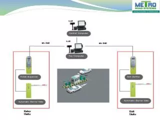
Page 2 of 9 of these individual systems. This will involve searching for the optimal and feasible design procedures, finding the necessary components, and verifying the operation once the design is completed and implemented. Once this has been completed, the long-term goal will be to integrate these two systems together, transmit data wirelessly and test the accuracy of the entire project as a whole. 3. Design Choices and Performance Figure 1 – Project Block Diagram Criteria Due to the complexity of this project, this project 2. Problem Statement would be limited to: This project consists of two main systems image Ø Straight ahead parking. processing, and embedded control. To successfully Ø Daylight driving conditions work on these two parts and implement them Ø Clear view only, nothing to block the together, there are three main problems that must be vision resolved: Ø Clear parking lots, no obstacles on the 1. How to execute the image processing? vehicle’s way 2. How to realize the wireless transmission Ø A distinguished red parking sign of the data? 3. How to appropriately control the robot 4. Details of Design once the embedded control system 4.1 Design tasks receives the transmitted data? Hardware Tasks: The challenge in the image processing system is to - The following tasks were completed to meet the be able to recognize the parking spot and calculating hardware/interface portion of the project: Robot Motion the curve function that will control the robot’s § motion. The embedded control system must be able Ø Stop function based on feedback system of to correctly receive the data transmitted and perform detected image and speed. error detection and correction to the transmitted Ø Speed inversely proportional to size of signal to allow optimal accuracy in controlling the image, as image is larger (closer to robot. The goal of the project is to break the design camera), speed becomes smaller. procedure in to two main parts image processing and Ø Centering of robot to an object also based embedded control. The goal is to complete the design
Page 3 of 9 Ø The speed of the DC motors are on feedback system of location of detected image with respect to center. being driven forward only due to the Ø When object is right of center point, turn max duty cycle generated by the robot to the left where the speed of PWM signal. the turn is depended on the pixel § Constructing the External Circuits difference to center. § Research/Order electronics Ø Robot circuit components needed Ø Level shifting circuit § Interfacing the Software with the § Testing Hardware This figure represents the design Ø Interfacing the image processing code in overview of the vehicle: Matlab with the robot. Ø Using characters to communicate the robot speed from the PC to the PIC16F690 § Building a wireless communication between the PC and the robot. Ø Transmitter /Receiver: Using Transmitter/Receiver to control a DC motor wirelessly Ø Building a level shifting circuit: We can’t Figure 2 – Project Overview connect the transmitter to the PC because Robot chassis the PC voltage is up to 12V. The ball caster was constructed using the instructions provided with the part. The ball caster was basically used to eliminate the use of two more wheels. With the use of just two rear wheels, more connections, § Generating PWM to control the and codes to control those wheels can be speed of the DC motor implemented. The gear shaft motors were mounted on the two wheels using two screws and rubber tubing was mounted over the wheels to maintain
Page 4 of 9 Voltage Regulator traction. The wheels were mounted at the rear of the project box using the four L-brackets. The ball caster +5 Voltage Source: The voltage regulator is was mounted at the front of the project box using made up of a 9volt battery, 7805 voltage regulator screws and two small plastic plates to raise it to the chip, 47μF capacitor, and 1N4007 diode. The 47μF level of the wheels. The breadboard was placed in the capacitors are for reducing noise and making sure we interior of the project box. get a constant clean 5v power supply and the diode Quadruple Half-H Driver & DC Wheel Motors: is to prevent current from flowing back into the To accomplish the objective, this portion of the circuit once the power is switched off. PICAXE(PIC16F690): design project consisted of a quadruple half-h bridge, the motor control circuitry. The quadruple The PIC16F microcontroller we selected is basically half-H driver is used for bidirectional control of the a general PIC chip developed by “Microchip,” with two DC motors. For the motor driver circuit, the proprietary Revolution Education code pre-installed. Basic X pins 9, 10, 11, and 12 were wired directly As such if the PIC chip is ordered from Microchip it to the Motor Driver Pins 2, 7, 15, and 10, WILL NOT function. respectively. The corresponding outputs of these The output of the receiver device is connected to motor driver pins (3, 6, 14, and 11) were wired to one of the input ports; Rb7, Rb5 & Rb6. RC0 RC1 the leads of the two motors. Vcc1 and the 1,2 and 3,4 & RC2 are used as output ports corresponding to enables were wired to the 5V regulator while Vcc2 the output of the receiver device. The motor driver was wired directly to the positive terminal of the enable pins will be driven by a pulse width second 9Volt battery. A separate battery modulator (PWM) generated by the PIC which will (particularly one at 9V) was found to be necessary allow the user to adjust the speed of the motors. The in order to provide enough power to drive the inputs designated to show if the motors are on/off motors. Motor Driver pins 5 and 12 were grounded. and their direction of turns will come from Port C of See figure3 the PIC chip (RC1, RC2, RC3, and RC4). Through these ports, the PIC is outputting the PWM signals. DC motor speed control is implemented through the use of Pulse width modulator (PWM). A PWM controller switches the motor on in a series of pulses. To control the motor speed, it varies/modulates the width of the pulses. The PWM resolution is defined as the maximum number of pulses that you can pack into a PWM period. The Max Duty cycle is set at 13 pulses which correlate Figure 3 – The motor control circuitry
Page 5 of 9 with 100% duty cycle. Note, the numbers 1 through supported by the PICAXE, etc. When the 13 correlate with the 0%100% duty cycle. The programming editor is first started it pops open a number of pulses also correlates with a set of small menu. Transmitter stage: characters from A to Z. These characters are what are communicated from the PC to the Vehicle. The In this stage a laptop is used and connected to the character A is 0% duty cycle, so all functions will USB which in turn is connected to RS232 (See stop at this point. These characters are used to figure 4). An RS232 female header is also required generate different PWM signals to control the front to send the matlab codes over the transmitter. Wires and back DC motors. were soldered to pins 2, 3 and 5 on the header and The letter a will be read by the PIC16F690 connect to the transmitter circuit. microprocessor through the level shifting circuit and the PIC will output a PWM signal with maximum duty cycle (%100). Circuit Board The circuit board contained all the necessary microchips; LED’s, wires, and resistors that were used in order to operate the robot. In order to make sure all components were not disconnected; I strengthened the board by soldering the components unto the circuit board. Figure4 – RS 232: 9 pin connection scheme Support Tools A compiler for programming the PICAXE Since RS-232 communication uses voltage chips is available from their main developer website. up to ±12V and it uses an inverse logic, then the It is listed as “PICAXE Programming Editor” under level shifting circuit can be utilized efficiently to their “Software” section. It is a BASIC compiler fulfill these requirements. The level shifting hence all codes will have to be written in BASIC. connects to the serial port pins using an individual The compiler comes complete loaded with three socket where wires from the RF transmitter and hefty manuals that have complete and detailed receiver are soldered to pins 2 and 3, and a wire is information on how to program the PICAXE chips, soldered to pin 5, which is ground. the necessary connections needed to download a program to the PICAXE, all BASIC commands
Page 6 of 9 To complete the image processing, used the following steps to get to the final results: · Detecting the parking spot. · Draw an ellipse around the parking spot and find the center of the ellipse. · Figure5 – Level Shifting Circuit Finding the curve between the center and the current vehicle position. From there, the data retrieved from the · Sending the information to the Matlab program, via serial port, is decoded by the controlling microprocessor for level shifting circuit (see figure 5). The appropriate appropriate corrective action. data from the level shifting circuit is sent to the PIC microprocessor. The PIC chip is then connected to the H-Bridge motor driver which the motors will Detecting the parking spot: also be connected to. Image processing For simplicity, a red rectangle was used to distinguish the parking spot. The camera has to see Image processing is selected as the best option to the red rectangle parking spot. When an image is implement automatic steer control for self parking taken and the parking spot is not there, nothing would system. The camera is controlled by Matlab to play be returned to matlab and another image is to be a video and take images. An image is to be taken by taken. If the image has a picture of the red rectangle, the camera and gets stored in the computer for further then everything is filtered from the picture except for processing. The image is to be analyzed and the red rectangle. A picture of just the red rectangle processed by Matlab. is returned to matlab. To decide on the direction, an ellipse is drawn around the red rectangle. Two lines are drawn inside the ellipse, one as a length and the Wireless Camera: other as the width of the ellipse. The length of the A wireless camera, JMK WS-309AS was chosen for ellipse is essentially the direction of the parking spot. this design. This camera has the following The direction is where the car should go when specifications: parking. · Powered by +9v supply. · Connects to the monitor with AV cable. The goodness value is how good the shape is. This · AV to USB 2.0 converter is used to value is to determine if an ellipse is to be drawn capture the images on the computer.
Page 7 of 9 around the shape. If the value of the goodness is indicating that this is where the car is supposed to close to 1, then a shape is the parking sign. If the end up parking. The program would wait for this value of the goodness is way smaller than one or input from the user; and depending on this point, a close to zero, then the shape is not the parking sign, curve function would be drawn from this point to the but noise. vehicle’s position. Find the curve function. Auto Mode: The curve is the path between the center of the ellipse For the automatic mode, the robot will be driven and the current position of the vehicle. The curve without any input from the user. An ellipse would be function is generated using the calculations below. drawn around the shape. The direction would be Using a third-degree polynomial, a curve would be decided automatically based on the length of the drawn from the center of the ellipse to the current ellipse. A curve function would be generated and position of the vehicle. This curve is what is given drawn from the center of the ellipse to the vehicle’s to the car to follow until it gets to the parking spot. position. The robot is to decide where to go The midpoint of the curve labeled as “T” is defined; depending on the curve function. this point is the target of the car. As the car moves, this point moves ahead of it. The car will be always Calculations: looking at this midpoint between the car and the final destination. Figure =0 As an extra feature, I used both automatic and forced mode. =0 Forced Mode: For the forced mode, the driver has to direct the robot where to go. By clicking on the parking spot,
Page 8 of 9 go o d n e ss sh o u ld go o d n e ss sh o u ld b e ap p ro xim ate ly 1 b e ap p ro xim ate ly 1 If value of goodness is close to 1 an ellipse is to be drawn around the shape If value of goodness is smaller than one then the shape is just a noise 4.2F 4.2FINAL INAL S SYSTEM YSTEM The Autonomous Self Parking System is a safety feature to be added to vehicles. Although this system met the specifications set forth, a project is never truly completed. There are always improvements that can be made. There are few modifications before installing the system to vehicles. For this project, one improvement definitely is the image processing should deal with all obstacles that could be found on parking lots. Examples of obstacles would be another parked car, constructions, carts, or anything that could be harmed to the car if crashed. Most important modification would be considering different signs found in the parking lot including but not limited to stop signs, handicapped signs, and speed signs. Another modification would be the power supply. It would be necessarily to change the power supply configuration for the embedded controller system. Currently, three nine-volt batteries are used for this system, one for the motor, one for the microcontroller and one for the camera. The image processing is written using Matlab and is being executed from a laptop. For more efficient
Page 9 of 9 system, the codes should be written using a high level mounted camera. The wireless transmission worked language such as C/C++, this will reduce the memory as expected, only taking the transmitted signals required to store the code and the microprocessor specialized by adding three (@) signs before the power needed to execute the code in a timely manner command. and will therefore reduce the cost of the project and When testing we wasn’t sure how big should make it more appealing for potential customers. The we make the sign, or how bright the red color should system should be tested under all possible different be, however, after several trials, we decided on the driving conditions. Then, the result data should be size and the color of the sign. When testing the analyzed statistically to ensure that the probability accuracy of the image processing, it was found that the curve using 2nd degree polynomial wasn’t for an error to occur is very minimal. All components of this design were soldered into vector accurate enough, so I had to use a three degree board to save space, and to eliminate the potential polynomial to get the curve function to be as accurate parasitic capacitance that may be present when using as I want it to be. breadboards. The camera was mounted outside of 6. References the car and probably held in place. However, it is up to the manufacturer to decide on the final packaging 1. http://www.mathworks.com/matlabcentral/fileexchange/lo that’s attractive to the customers. adFile.do?objectId=2939&objectType=FILE Voice Recognition Security System Project from Cornell 4.3 Socio-Economic Issues University The Autonomous Self Parking System has http://instruct1.cit.cornell.edu/courses/ee476/FinalProjects some problems that cause concerns with safety /s2006/XL76_SL362/XL76%20SL362/ issues. The sign that the system is looking for is a 2. Image processing Toolbox red, assuming there are no red objects around, which http://www.mathworks.com/products/image/ very limited and not practical. However, for real-life use this system should not be limited to a particular 3. Matlab: An Introduction: Digital Image Processing I – 2006 By Esin Guldogan sign or color. 5. Test Results and Discussion The Autonomous Self Parking System is done with a successful degree of accuracy. The robot correctly executes the instructions sent from the computer corresponding to the taken picture by the