Download
1 / 22
240 likes | 613 Vues
Introduction to Simulating radio propagation models and COOJA ARM. One radio…. REFRACTION. REFLECTION. DIFFRACTION. … receiving a radio signal Typically 4 different categories Problem: What happens to the radio signal? (And how is sound quality affected?). SCATTERING.

E N D
Introduction toSimulating radio propagation modelsand COOJA ARM
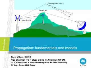
One radio… REFRACTION REFLECTION DIFFRACTION • … receiving a radio signal • Typically 4 different categories • Problem: • What happens to the radio signal? • (And how is sound quality affected?) SCATTERING
WSN radio model types • Unit Disk Graph • COOJA’s Standard Radio Medium • Bit Error Ratio (BER) • Collected statistical data (or empirical models) • Ray tracing
COOJA ARM • Advanced Radio Medium • “Advanced” when compared to “Standard” :) • Radio propagation models introduction • How ARM works
Wiki’s definitions • Radio Propagation “... is a term used to explain how radio waves behave when they are transmitted, or are propagated from one point on the Earth to another.” • Radio Propagation Model “... characterization of radio wave propagation as a function of frequency, distance and other conditions.”
Empirical models • Lots of different models exist • Outdoor • City, Terrain, Rain, Earth curvature • Okumura model built using data collected in Tokyo • Indoor • ITU Model for indoor Attenuation • Log Distance Path Loss Model • Typical parameters: frequency, distance, number of floors, coefficients tuned to different environments etc. • Above models based on empirical data
Analytical approach • Based on ray tracing • Calculates multi-path effects • Used in COOJA ARM
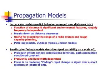
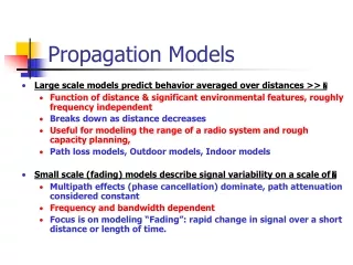
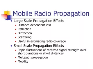
Small-scale vs. Large-scale • Small-scale effects • Sum of many received signal from different directions • Often Gaussian random • Scattering • Large-scale effects • Shadowing • Reflections
Free Space Propagation Model • (FSPL) • Predicts signal strength for LOS paths Antenna gains Wavelength Transmitted vs. received power Distance
Ray tracing in ARM • 2D positions • Supports attenuating obstacles • Only rectangles • Refractions • Reflections • Diffractions • Potential support: • Scatterings
Using ARM • Registers two plugins • Changing formula parameters • Visualizing radio coverage • Listens to all radios in the simulation • Transmitted power • Antenna gains • Packet lengths • SNR threshold • (Channel)
Default valueMay be radio specific Frequency: ~900 MHz Formula Viewer
From radio specification Default valuesMay be radio specific Formula Viewer
From radio specification Default valuesMay be radio specific Formula Viewer
FSPL mentioned earlier Fixed “penalty” constants FUTURE:Should be replaced by angle dependent formulas Maximum values used by ray tracer May become very time-consuming =) Formula Viewer
Property of obstacle type(wood, glass, metal) Formula Viewer
Area Viewer • Shows radios, obstacles and channel propagation
Area Viewer • Obstacles are set by analyzing the background image
Area Viewer • User may track ray paths from a transmitter to a point • Uses the current formula settings
Area Viewer • Show surroundings of transmitter: • Signal strength • SNR ratio • Probability of reception • Delay spread
Area Viewer Received signal strength vs. Probability of reception
Future work • Validate models • Parameter estimation / Model calibration • From actual measurements