Download
1 / 81
860 likes | 1.4k Vues
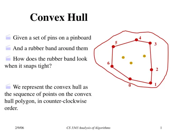
HULL FORM AND GEOMETRY. Intro to Ships and Naval Engineering (2.1). HULL FORM AND GEOMETRY. Intro to Ships and Naval Engineering (2.1). Factors which influence design:. Size Speed Seakeeping Maneuverability Stability Special Capabilities (Amphib, Aviation, ...).

E N D
HULL FORM AND GEOMETRY Intro to Ships and Naval Engineering (2.1)
HULL FORM AND GEOMETRY Intro to Ships and Naval Engineering (2.1) • Factors which influence design: • Size • Speed • Seakeeping • Maneuverability • Stability • Special Capabilities (Amphib, Aviation, ...) Compromise is required!
HULL FORM AND GEOMETRY Categorizing Ships (2.2) • Methods of Classification: • 1.0 Usage: • Merchant Ships (Cargo, Fishing, Drill, etc) • Naval and Coast Guard Vessels • Recreational Boats and Pleasure Ships • Utility Tugs • Research and Environmental Ships • Ferries
HULL FORM AND GEOMETRY Categorizing Ships (2.2) • Methods of Classification (con’t): • 2.0 Physical Support: • Hydrostatic • Hydrodynamic • Aerostatic • (Aerodynamic)
HULL FORM AND GEOMETRY Categorizing Ships (2.2)
HULL FORM AND GEOMETRY Categorizing Ships (2.2) • Hydrostatic Support (also know as Displacement Ships) Float by displacing their own weight in water • Includes nearly all traditional military and cargo ships and 99% of ships in this course • Small Waterplane Area Twin Hull ships (SWATH) • Submarines
Categorizing Ships (2.2) HULL FORM AND GEOMETRY • Aerostatic Support - Vessel rides on a cushion of air. Lighter weight, higher speeds, smaller load capacity. • Air Cushion Vehicles - LCAC: Opens up 75% of littoral coastlines, versus about 12% for displacement • Surface Effect Ships - SES: Fast, directionally stable, but not amphibious
Categorizing Ships (2.2) HULL FORM AND GEOMETRY • Hydrodynamic Support - Supported by moving water. At slower speeds, they are hydrostatically supported • Planing Vessels - Hydrodynamics pressure developed on the hull at high speeds to support the vessel. Limited loads, high power requirements. • Hydrofoils - Supported by underwater foils, like wings on an aircraft. Dangerous in heavy seas. No longer used by USN. (USNA Project!)
Categorizing Ships (2.2) HULL FORM AND GEOMETRY • Hydrostatic Support - Based on Archimedes Principle • Archimedes Principle - “An object partially or fully submerged in a fluid will experience a resultant vertical force equal in magnitude to the weight of the volume of fluid displaced by the object.”
Categorizing Ships (2.2) HULL FORM AND GEOMETRY • Archimedes Principle - The Equation where: FB = is the magnitude of the resultant buoyant force in lb = (“rho”) density of the fluidin lb • s2 / ft 4or slug/ft3 g = magnitude of accel. due to gravity (32.17 ft/s2) = volume of fluid displaced by the object in ft3
HULL FORM AND GEOMETRY How are these vessels supported? • Hydrostatic • Hydrodynamic • Aerostatic • A combination?
HULL FORM AND GEOMETRY Brain Teasers!
Representing Ship Designs HULL FORM AND GEOMETRY • Problems include: • Terms to use (jargon) • How to represent a 3-D object on 2-D paper • Sketches • Drawings • Artist’s Rendition
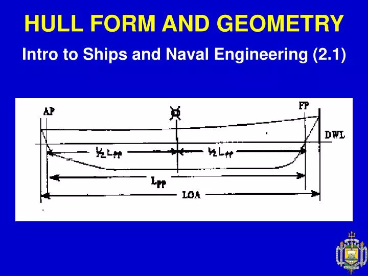
Basic Dimensions (2.3.3) HULL FORM AND GEOMETRY • Design Waterline (DWL) - The waterline where the ship is designed to float. • Stations - Parallel planes from forward to aft, evenly spaced (like bread). Normally an odd number to ensure an even number of blocks.
Basic Dimensions (2.3.3) HULL FORM AND GEOMETRY • Forward Perpendicular (FP) - Forward station where the bow intersects the DWL. Station 0. • Aft Perpendicular (AP) - After station located at either the rudder stock or the intersection of the stern with the DWL. Station 10. • Length Between Perpendiculars (Lpp) -Distance between the AP and the FP. In general the same as LWL (length at waterline).
Basic Dimensions (2.3.3) HULL FORM AND GEOMETRY • Length Overall (LOA) - Overall length of the vessel. • Midships Station ( ) - Station midway between the FP and the AP. Station 5 in a 10-station ship. Also called amidships.
HULL FORM AND GEOMETRY Hull Form Representation (2.3.0-2.3.3) • Lines Drawings - Traditional graphical representation of the ship’s hull form. “Lines” Half-Breadth Sheer Plan Body Plan
HULL FORM AND GEOMETRY Hull Form Representation (2.3.0-2.3.3) Body Plan Half-Breadth Plan Sheer Plan Lines Plan
HULL FORM AND GEOMETRY Hull Form Representation (2.3.0-2.3.3) • Half-Breadth Plan (“Breadth” = “Beam”)
HULL FORM AND GEOMETRY Hull Form Representation (2.3.0-2.3.3) • Half-Breadth Plan (“Breadth” = “Beam’) • Intersection of horizontal planes with the hull to create waterlines. (Parallel with water.)
Hull Form Representation (2.3.0-2.3.3) HULL FORM AND GEOMETRY • Sheer Plan • Parallel to centerplane • Pattern for construction of longitudinal framing.
HULL FORM AND GEOMETRY Hull Form Representation (2.3.0-2.3.3) • Sheer Plan • Intersection of planes parallel to the centerline plane define the Buttock Lines. These show the ship’s hull shape at a given distance from the centerline plane.
Hull Form Representation (2.3.0-2.3.3) HULL FORM AND GEOMETRY • Body Plan • Pattern for construction of transverse framing.
HULL FORM AND GEOMETRY Hull Form Representation (2.3.0-2.3.3) • Body Plan • Intersection of planes parallel to the centerline plane define the Section Lines. • Section lines show the shape of the hull from the front view for a longitudinal position
HULL FORM AND GEOMETRY Table of Offsets (2.4) • The distances from the centerplane are called the offsets or half-breadth distances.
HULL FORM AND GEOMETRY Table of Offsets (2.4) • Used to convert graphical information to a numerical representation of a three dimensional body. • Lists the distance from the center plane to the outline of the hull at each station and waterline. • There is enough information in the Table of Offsets to produce all three lines plans.
Hull Form Characteristics (2.5) HULL FORM AND GEOMETRY • Depth (D) - Distance from the keel to the deck. • Remember “Depth of Hold.” • Draft (T) - Distance from the keel to the surface of the water. • Beam (B) - Transverse distance across each section. • Half-Breadths are “half of beam”. Flare Tumblehome
Hull Form Characteristics (2.5) HULL FORM AND GEOMETRY • Keel (K) - Reference point on the bottom of the ship and is synonymous with the baseline.
Centroids (2.6) HULL FORM AND GEOMETRY • Centroid – The geometric center of a body. • Center of Mass - A “single point” location of the mass. • Better known as the Center of Gravity (CG). • CG and Centroids are only in the same place for uniform (homogenous) mass!
Centroids (2.6) HULL FORM AND GEOMETRY • Centroids and Center of Mass can be found by using a weighted average.
What is the longitudinal center of gravity of this 18 foot row boat? Hull: 150 lb at station 6 Seat: 10 lb at station 5 Rower: 200 lb at station 5.5 HULL FORM AND GEOMETRY
Center of Flotation (F or CF) (2.7.1) HULL FORM AND GEOMETRY • The centroid of the operating waterplane. • (The center of an area.) • The point about which the ship will list and trim! • Transverse Center of Flotation (TCF) - Distance of the Center of Flotation from the centerline.(Often = 0 feet)
Center of Flotation (F or CF) (2.7.1) HULL FORM AND GEOMETRY • Longitudinal Center of Flotation (LCF) - Distance from midships (or the FP or AP) to the Center of Flotation. • The Center of Flotation changes as the ship lists or trims because the shape of the waterplane changes.
Center of Buoyancy (B or CB) (2.7.2) HULL FORM AND GEOMETRY • Centroid of the Underwater Volume. • Location where the resultant force of buoyancy (FB) acts. • Transverse Center of Buoyancy (TCB) - Distance from the centerline to the Center of Buoyancy.
Center of Buoyancy (B or CB) (2.7.2) HULL FORM AND GEOMETRY • Vertical Center of Buoyancy (VCB or KB) - Distance from the keel to the Center of Buoyancy. • Longitudinal Center of Buoyancy (LCB) - Distance from the amidships or AP or FP to the Center of Buoyancy. • Center of Buoyancy moves when the ship lists or trims (TCB).
Center of Buoyancy (B or CB) (2.7.2) HULL FORM AND GEOMETRY Which way is it moving? Fwd or Aft?
Fundamental Geometric Calculations (2.8) HULL FORM AND GEOMETRY • A ship’s hull is a complex shape which cannot be described by a mathematical equation! • How can centroids, volumes, and areas be calculated? (Hint: you can’t integrate!) • Use Numerical Methods to approximate an integral! • Trapezoidal Rule (linear approximation) • Simpson’s Rule (quadratic approximation)
Fundamental Geometric Calculations (2.8.1) HULL FORM AND GEOMETRY Example: Waterplane Calculation (Trapezoidal)
Fundamental Geometric Calculations (2.8.1) HULL FORM AND GEOMETRY • Simpson’s Rule - Used to integrate a curve with an odd number of evenly spaced ordinates. (Ex. Stations 0 - 10)