Download
1 / 26

E N D
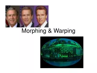
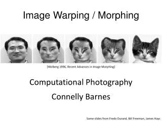
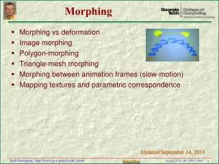
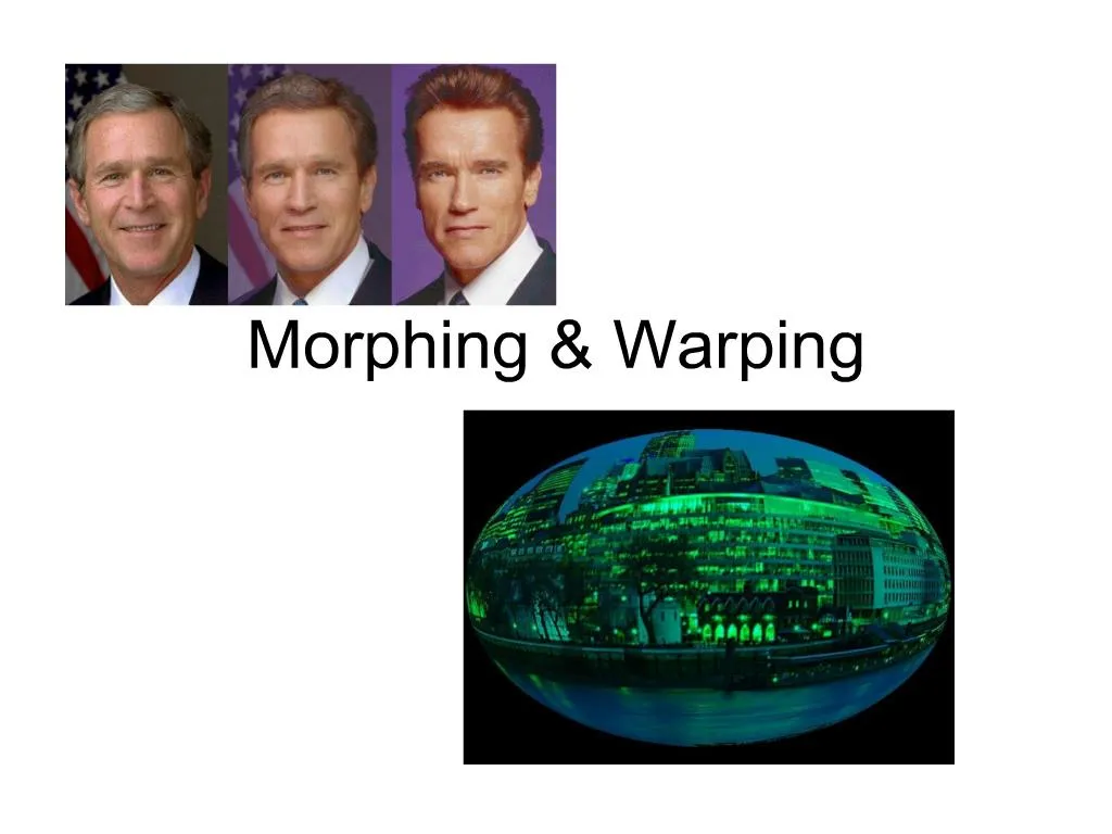
1. Morphing & Warping
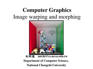
3. What is texture mapping? Texture mapping T(u,v) = (x,y,z), mapping specified by vertex pairs.
How does it work?
4. Some details (Thanks, Wikipedia!) Affine texture mapping directly interpolates a texture coordinate ua between two endpoints and u0 and u1:
ua = (1-a)u0 + au1 where 0 = a = 1
A little openGL, if you�re curious
glTexParameteri(GL_TEXTURE_2D, GL_TEXTURE_MAG_FILTER, GL_NEAREST);
glTexParameteri(GL_TEXTURE_2D, GL_TEXTURE_MIN_FILTER, GL_LINEAR);
5. 2D Morphing
6. 2 pass mesh Warping (Smythe 90) Idea: use splines to specify curves on each image
get control of warping
Input
Source & destination images
2D array of control points in source
2D array of control pts in destination
7. To animate S D Need to animate source grid to destination grid to produce intermediate grids I (could be multiple passes)
At each animation frame, need to generate intermediate image from S & I
8. Steps
9. Steps For Each Frame in Animation for 2 different images
10. Magnification and Minification
11. Feature Based Image Metamorphisis (Beier and Neely, �92) Instead of using curves, use line-pairs to specify correspondence
Instead of 2 pass approach, 1 pass that calculates weighted contributions from each line pair to each pixel
Input:
Source image
Destination image
Line pairs PQS PQD
12. Step For each frame between source S & destination D
Interpolate PQS & PQD to generate intermediate �destination shape�
Warp S to intermediate destination shape
Warp d to intermediate destination shape
Cross dissolve warped images
Save result as intermediate frame
13. Field Morphing For a Single Line Pair Given P�Q� in S, and PQ in D
Parameterize length as u:0 .. 1 over PQ and scaled over P�Q�
Given some point X, distance v from PQ
u = || X-P|| cos ?/||Q-P|| (% distance from P, along PQ )
v = [(X � P) -(Q-P)]/||Q-P||
Where -(m) is defined -1/m � e.g. 1/(P-Q)
V is the projection of of P-X onto the perpendicular vector V
14. Field Morphing For a Single Line Pair X� = P� + u� (Q� � P�) + [v�-(Q�-P�)] / ||Q�-P�||
15. Single Line Pair
16. u = (X-Pd) �(Qd-Pd) / |Qd-Pd|2
u = (20,-30)�(70,0) / 702
u = 1400/4900 = 2/7
v = | (X-Pd) x (Qd-Pd) / |Qd-Pd|2 |
v =|(20,-30) x (70,0) / 702 | note: 2D cross product = determinant
v = 2100/4900 = 3/7
17. T = Qs - Ps=(0,70)
S = (Ty, - Tx) = (70,0)
X� = Ps + uT + vS
X� = (10,10) + 2/7 (0,70) + 3/7 (70,0)
X� = (10,10) + (0,20) + (30,0) = (40,30)
18. Multiple Lines Think Shepard�s algorithm
For point X in the source image, we calculate X� for each of the line pairs
Then use a weighted sum to ultimately find the destination X�
19. The details X� is calculated from X and a weighted set of distances from X
X� = X +S DiWi / ( S Wi) , n = number of lines
Di = Xi� � X
Wi = [ lengthiP/ (a+ disti )]b
P =importance to line length. Increasing P increases the effect of longer lines
b = how influence falls off with distance (0.5�2). What if b=0?
disti = distance from X to line i; as distance increases, weight decreases
a = prevents division by zero, can also help with smoothing the lines themselves
20. 3D Morphing Place link here
21. 3D Morphing Imagine you have two 3D meshes;how to morph between them?
Issues:
Getting a mapping between polygons of the 2 objects
Different numbers of polygons
Down sample or increase sampling?
Imagine you have two 3D volumes;how to morph between them?
22. Surface Morphing With Different Numbers of triangles Use simplification (edge collapse techniques) to simplify correspondence
Make sure it is reversible/tracks changes
User needs to simplify vertices around features
23. Feature Based Volume Metamorphosis Extension of idea of Beier and Neely
Instead of simple line pairs, element pairs
Elements have
�dimensionality�: can be a point, line, rectangular plane or volume (box)
spatial configuration:
Local coordinate system and origin
Scaling factor (features extent along local axes)
Beier and Neely method applied to get new mesh (handwaving..)
24. Another Method: Fourier Volume Mapping Object volume must be described by a function
FT: integrate over [function*e-i2pft]
25. Pluses and Minuses Resolves correspondence issue (move out of cartesian space into frequency space)
A clean process but less than ideal results (better on some shapes than others)
No guarantee features will stay where they should
26. 3D Morphing Idea: input triangle mesh with different number of vertices
Use simplification to simplify correspondence problem