Download
1 / 1
10 likes | 444 Vues
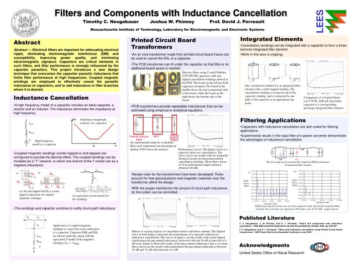
L A. L B. L C. Comparison of a United Chemi-con U767D, 2200 F electrolytic capacitor to a corresponding prototype integrated filter element. Impedance magnitude response of a capacitor.

E N D
LA LB LC Comparison of a United Chemi-con U767D, 2200 F electrolytic capacitor to a corresponding prototype integrated filter element. Impedance magnitude response of a capacitor One construction method for an integrated filter element with a center-tapped winding. The cancellation winding is wound on top of the capacitor winding, and is connected to one plate of the capacitor at an appropriate tap point. Network Analyzer Input DUT Network Analyzer Output High frequency model of a capacitor An experimental setup for evaluating filters and components incorporating an Agilent 4395A network analyzer. LESL b) a) RESR 11 M i1 C i1 M 22 11 22 i2 i2 a) b) a) LA LB b) The test setup used to measure the conducted EMI performance of integrated filter element. (a) An end-tapped and (b) a center-tapped connection of coupled magnetic windings. LC LISN Power (dBm) LISN Power (dBm) LESL RESR LA LB LC End-tapped LM L22-LM L11-LM Center-tapped L11+LM L22+LM -LM C Frequency (Hz) Frequency (Hz) An equivalent circuit model for the windings. Filters and Components with Inductance Cancellation LEES Timothy C. Neugebauer Joshua W. Phinney Prof. David J. Perreault Massachusetts Institute of Technology, Laboratory for Electromagnetic and Electronic Systems • Integrated Elements • Cancellation windings can be integrated with a capacitor to form a three-terminal integrated filter element. • Work in this area is ongoing. • Printed Circuit Board Transformers • An air core transformer made from printed circuit board traces can be used to cancel the ESL of a capacitor. • The PCB transformer can fit under the capacitor so that little or no additional board space is needed. • PCB transformers provide repeatable inductances that can be estimated using empirical or analytical equations. • Design rules for the transformers have been developed. Rules account for how ground planes and magnetic materials near the transformer affect the design. • With the proper transformer the amount of shunt path inductance (to first order) can be controlled. • Abstract • Abstract --- Electrical filters are important for attenuating electrical ripple, eliminating electromagnetic interference (EMI) and susceptibility, improving power quality, and minimizing electromagnetic signature. Capacitors are critical elements in such filters, and filter performance is strongly influenced by the capacitor parasitics. This project introduces a new design technique that overcomes the capacitor parasitic inductance that limits filter performance at high frequencies. Coupled magnetic windings are employed to effectively cancel the parasitic inductance of capacitors, and to add inductance in filter branches where it is desired. Discrete filters using Cornell Dubilier 935C4W10K capacitors with end-tapped cancellation windings printed in the PCB. The board on the left has both capacitors mounted. The board in the middle shows the top (component) side of the board, while the board on the right shows the bottom side of the board. • Inductance Cancellation • A high frequency model of a capacitor includes an ideal capacitor, a resistor and an inductor. The inductance dominates the impedance at high frequency. • Coupled magnetic windings (center-tapped or end-tapped) are configured to provide the desired effect. The coupled windings can be modeled as a “T” network, in which one branch of the T model can be a negative inductance. • The windings and capacitor combine to nullify shunt path inductance. • Filtering Applications • Capacitors with inductance cancellation are well suited for filtering applications. • Experimental results in the input filter of a power converter demonstrate the advantages of inductance cancellation. Performance curves. The higher curve is a capacitor alone (no cancellation). The lower curves are results with six nominally identical circuits incorporating printed cancellation windings. More than a factor of 10 in performance improvement is obtained (20 dB). LISN power spectra for the case of (a) the capacitor alone and (b) the integrated filter element. The converter was operated at 50% duty cycle at 10 A DC output current. Published Literature T. C. Neugebauer, J. W. Phinney, and D. J. Perreault, “Filters and components with inductance cancellation,” 2002 IEEE Industrial Applications Society Annual Meeting, October 2002, pp. 939-947. T. C. Neugebauer and D. J. Perreault, “Filters with inductance cancellation using Printed Circuit Board Transformers,” 2003 Power Electronics Specialist Conference, June 2003. Application of coupled magnetic windings to cancel the series inductance of a capacitor. Capacitor ESR and ESL are shown explicitly, along with the equivalent T model of the magnetic windings. Effects of varying degrees of cancellation below and above optimal. The highest curve in both figures represents the performance of a capacitor without any inductance cancellation. The curves in figure a are the results with center-tapped transformers having mutual inductances between 6 nH and 26 nH at intervals of 4 nH each. Figure b shows the results of having a mutual inductance that is too large; these curves are the results with transformers having mutual inductances between 26 nH and 32 nH with intervals of 2 nH. Acknowledgments United States Office of Naval Research