Download
1 / 46
560 likes | 1.65k Vues
The Electronic Spectra of Coordination Compounds. Introduction. Many transition metal complexes are colored. This is due to transitions of electrons between the molecular orbitals that are formed largely by the d orbitals on the metal.

E N D
Introduction Many transition metal complexes are colored. This is due to transitions of electrons between the molecular orbitals that are formed largely by the d orbitals on the metal. Many transitions are in the visible range, with the color of the complex taking on the complementary color of the frequency or frequencies absorbed.
General Features Absorption bands in electronic spectra are usually broad, and occur much more rapidly than molecular vibrations. As a result, the spectra represent a “snapshot” of molecules in various vibrational and rotational states.
General Features Extinction coefficients will range from <1 up to 50,000 M-1cm-1 depending upon the type of electronic transition and whether it is permitted based on selection rules.
Selection Rules Electronic transitions obey the following selection rules: 1. ∆S = 0. Electrons cannot change spin. 2. The Laporte rule states that there must be a change in parity. Only gu or ug transitions are allowed. Thus, all dd transitions are forbidden by this selection rule.
The UV/Vis spectra of transition metal complexes show the transitions of the electrons. Analysis of these spectra can be quite complex.
Summary of Observations-First Row Transition Metal Complexes (high spin) • d1, d4, d6 and d9 complexes show one absorption. • d2, d3, d7 and d8 complexes show three absorptions, with the 3rd peak often obscured. • d5 complexes show very weak, sharp absorptions.
Note that even the single peaks show “side peaks” or overlapping bands of absorption.
Electron Spectra The UV/Vis spectra are used to determine the value of ∆o for the complex. The spectra arise from electronic transitions between the t2g and eg sets of molecular orbitals. Electron-electron interactions can greatly complicate the spectra. Only in the case of a single electron is interpretation of the spectrum straightforward.
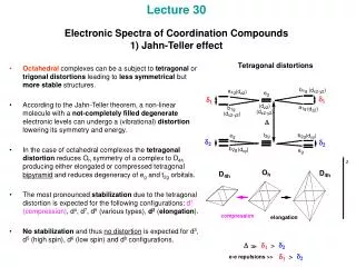
Obtaining ∆o For a d1 configuration, only a single peak is seen. It results from the electron promotion from the t2g orbitals to the eg orbitals. The “toothed” appearance of the peak is due to a Jahn-Teller distortion of the excited state. The energy of the peak = ∆o.
General Observations d1, d4, d6 and d9 usually have 1 absorption, though a side “hump” results from Jahn-Teller distortions.
General Observations d2, d3, d7 and d8 usually have 3 absorptions, one is often obscured by a very intense charge transfer band.
General Observations d5 complexes consist of very weak, relatively sharp transitions which are spin-forbidden, and have a very low intensity.
Electronic Transitions Absorption of light occurs when electrons are promoted from lower to higher energy states. Interactions between electrons causes more than one peak in the UV/Vis spectra of these complexes. The electrons are not independent of each other, and the spin angular momenta and orbital angular momenta interact.
Electronic Transitions The interaction of orbital angular momenta (ml values) and spin angular momenta (ms values) is called Russel-Saunders or LS coupling. The lower transition metals (4d and 5d) undergo further coupling (called j-j coupling or spin-orbit coupling).
3d Multi-electron Complexes The interactions produce atomic states called microstates that are described by a new set of quantum numbers. ML = total orbital angular momentum =Σml MS = total spin angular momentum = Σms
Determining the Energy States of an Atom A microstate table that contains all possible combinations of ml and ms is constructed. Each microstate represents a possible electron configuration. Both ground state and excited states are considered.
Energy States Microstates would have the same energy only if repulsion between electrons is negligible. In an octahedral or tetrahedral complex, microstates that correspond to different relative spatial distributions of the electrons will have different energies. As a result, distinguishable energy levels, called terms are seen.
Energy States To obtain all of the terms for a given electron configuration, a microstate table is constructed. The table is a grid of all possible electronic arrangements. It lists all of the possible values of spin and orbital orientation. It includes both ground and excited states, and must obey the Pauli Exclusion Principle.
Constructing a Microstate Table Consider an atom of carbon. Its highest occupied orbital has a p2 electron configuration. Microstates correspond to the various possible occupation of the px, py and pz orbitals.
Constructing a Microstate Table ml = +1 0 -1 microstate: Configurations: ___ ___ ___ (1+,0+) ___ ___ ___ (0+,-1+) ___ ___ ___ (1+,-1+) These are examples of some of the ground state microstates. Others would have the electrons (arrows) pointing down.
Constructing a Microstate Table ml = +1 0 -1 microstate: Configurations: ___ ___ ___ (1+,1-) ___ ___ ___ (0+,0-) ___ ___ ___ (-1+,-1-) These are examples of some of the excited state microstates.
Microstate Table for p2 For the carbon atom, ML will range from +2 down to -2, and MS can have values of +1 (both electrons “pointing up”), 0 (one electron “up”, one electron “down), or -1 (both electrons “pointing down”).
Microstate Table for p2 MS The table includes all possible microstates.
Constructing a Microstate Table Once the microstate table is complete, the microstates are collected or grouped into atomic (coupled) energy states.
Constructing a Microstate Table For two electrons, L = l1+ l2, l1+ l2-1, l1+ l2-2,…│l1- l2│ For a p2 configuration, L = 1+1, 1+1-1, 1-1. The values of L are: 2, 1 and 0. L is always positive, and ranges from the maximum value of Σl.
Constructing a Microstate Table For two electrons, S = s1+ s2, s1+ s2-1, s1+ s2-2,…│s1- s2│ For a p2 configuration, S = ½ + ½ , ½ + ½ -1. The values of S are: 1 and 0.
Atomic Quantum Numbers Quantum numbers L and S describe collections of microstates, whereas ML and MS describe the individual microstates themselves.
Constructing a Microstate Table The microstate table is a grid that includes all possible combinations of L, the total angular momentum quantum number, and S, the total spin angular momentum quantum number. For two electrons, L = l1+ l2, l1+ l2-1, l1+ l2-2,…│l1- l2│ S = s1+ s2, s1+ s2-1, s1+ s2-2,…│s1- s2│
Constructing a Microstate Table Once the microstate table is complete, all microstates associated with an energy state with specific value of L and S are grouped. It doesn’t matter which specific microstates are placed in the group. Microstates are grouped and eliminated until all microstates are associated with a specific energy state or term.
Term Symbols Each energy state or term is represented by a term symbol. The term symbol is a capitol letter that is related to the value of L.
Term Symbols The upper left corner of the term symbol contains a number called the multiplicity. The multiplicity is the number of unpaired electrons +1, or 2S+1.
Microstate Table for p2 MS Eliminate microstates with ML=+2-2, with Ms=0.
Microstate Table for p2 MS These microstates are associated with the term 1D.
Microstate Table for p2 MS Eliminate microstates with ML=+1-1, with Ms=+1-1
Microstate Table for p2 MS Eliminate microstates with ML=+1-1, with Ms=+1-1
Microstate Table for p2 MS These microstates are associated with the term 3P.
Microstate Table for p2 MS One microstate remains. It is associated with the term 1S.
Term States for p2 The term states for a p2 electron configuration are 1S, 3P, and 1D. The term symbol with the greatest multiplicity and highest value of ML will be the ground state. 3P is the ground state term for carbon.
Determining the Relative Energy of Term States 1. For a given electron configuration, the term with the greatest multiplicity lies lowest in energy. (This is consistent with Hund’s rule.) 2. For a term of a given multiplicity, the greater the value of L, the lower the energy.
Determining the Relative Energy of Term States For a p2 configuration, the term states are 3P, 1D and 1S. The terms for the free atom should have the following relative energies: 3P< 1D <1S
Determining the Relative Energy of Term States The rules for predicting the ground state always work, but they may fail in predicting the order of energies for excited states.
Energy States for a d2 Configuration A microstate table for a d2 electron configuration will contain 45 microstates (ML = 4-4, and MS=1, 0 or -1) associated with the following terms: 1S, 1D, 1G, 3P, and 3F
Energy States for a d2 Configuration • Problem: Determine the ground state of a free atom with a d2 electron configuration, and place the terms in order of increasing energy. 1S, 1D, 1G, 3P, and 3F
Determining the Ground State Term We only need to know the ground state term to interpret the spectra of transition metal complexes. This can be obtained without constructing a microstate table. The ground state will a) have the maximum multiplicity b) have the maximum value of ML for the configuration obtained in part (a).