Download
1 / 9
90 likes | 338 Vues
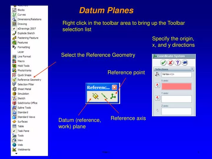
Specify the origin, x, and y directions. Select the Reference Geometry. Reference point. Reference axis. Datum (reference, work) plane. Datum Planes. Right click in the toolbar area to bring up the Toolbar selection list. Reference Features. The reasons you may need Reference features.

E N D
Specify the origin, x, and y directions Select the Reference Geometry Reference point Reference axis Datum (reference, work) plane Datum Planes Right click in the toolbar area to bring up the Toolbar selection list PDM 1
Reference Features The reasons you may need Reference features • To locate a sketch for a new feature where a part surface is not available; construct a reference plane to sketch. • To establish a plane or an edge for dimensioning; construct reference plane or reference axis. • To provide a point for rotating or an axis for revolving features or patterns; construct reference point or reference axis • To establish an intermediate position that is required to define other reference plane; construct a reference plane PDM 1
Methods for creating a reference plane Select a point and a line Specify three points Reference Planes Reference plane is a rectangular plane that is tied to the model parametrically and is infinitely large. There is no limit on the number of reference planes and they can be used to create new sketches for feature operations. PDM 1
Reference Planes Parallel to a plane and passing through a certain point PDM 1
Select the top plane and sketch a line thru point A Select reference plane at an angle option A Select the top face and the second line to create the plane A A Draw another line perpendicular to the first one at point A Reference plane Reference Planes Create a plane passing thru a desired point (A) making an angle with another plane (top) PDM 1
Select cutting plane Select the part of the object to cut Check Consume cut bodies Reference Planes Cutting an object with a plane Select Insert, Features and choose Split PDM 1
Reference Planes Creating an offset plane Select a face and specify the offset and the number of reference planes Reference plane Offset distance PDM 1
Select curve and point Reference Planes – Perpendicular (Normal) to a Curve Create planes perpendicular to a curve at a certain point. Useful for sketching profiles for sweep and loft (sweeping and blending). Select Normal to Curve PDM 1
Reference plane Select Surface and point Reference Planes – on Surface Create a reference plane tangent to a curved surface at a specific point. Select On Surface option PDM 1