Download

1 / 19
190 likes | 514 Vues
Semiconductor Device Modeling and Characterization EE5342, Lecture 30 Spring 2003. Professor Ronald L. Carter ronc@uta.edu http://www.uta.edu/ronc/. Gummel-Poon Static npn Circuit Model. Intrinsic Transistor. C. R C. I BR. B. R BB. I LC. I CC - I EC = {IS/Q B }*

E N D
Semiconductor Device Modeling and CharacterizationEE5342, Lecture 30Spring 2003 Professor Ronald L. Carter ronc@uta.edu http://www.uta.edu/ronc/
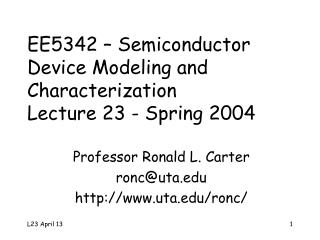
Gummel-Poon Staticnpn Circuit Model Intrinsic Transistor C RC IBR B RBB ILC ICC -IEC = {IS/QB}* {exp(vBE/NFVt)-exp(vBC/NRVt)} IBF B’ ILE RE E
IBF = IS expf(vBE/NFVt)/BF ILE = ISE expf(vBE/NEVt) IBR = IS expf(vBC/NRVt)/BR ILC = ISC expf(vBC/NCVt) ICC -IEC = IS(exp(vBE/NFVt - exp(vBC/NRVt)/QB QB= {+ [+ (BFIBF/IKF + BRIBR/IKR)]1/2} (1 - vBC/VAF - vBE/VAR )-1 Gummel Poon npnModel Equations
VBIC Model Overview [5] • Self-heating effects included • Improved Early effect modeling • Quasi-saturation modeling • Parasitic substrate transistor modeling • Parasitic fixed (oxide) capacitance modeling • An avalanche multiplication model included • Base current is decoupled from collector current
CAD Tools Support for VBIC • Hspice [4] • Does not support PNP device • Does not scale with “Area” and “M” terms • Spectre [5] • Support both NPN and PNP devices • scale with “Area” and “M” term • HPADS • No temperature nodes (“dt” and “tl”), so unable to simulate thermal coupling effects
Parameters Description Spectre [4] Hspice [5] Name Default Name Default Temperature rise of the device from ambient trise 0 dtemp 0 Ambient temp. temp 27 temp 25 Parameters measurement temperature tnom 27 tnom 25 tref 27 Temperature Designations for VBIC
Using VBIC in Spectre [5] Name c b e [s] [dt] [tl] ModelName parameter=value ... • Selft=1 and Rth>0 to enable Self-heating • 1 volt at the temperature nodes = 1 degree in temperature • “tl” node represents the initial local temperature of device which always corresponds to trise+temp • “dt” node represents the rise above trise+temp caused by thermal dissipation, whose value equals V(dt)-V(tl) • Device temperature=V(dt)-V(tl)+trise+temp
Using VBIC in Cadence • Need explicit external temperature nodes in the symbol to model inter-device thermal coupling by • Connecting thermal network between “dt” nodes, or • Adding VCVS between “tl” and “tlr” node • Customized VBIC 6-terminal (5-pin) symbol
Model Conversion • Most BJTs are defined with SGP model • A conversion from SGP to VBIC is needed • Only approximate conversion is possible • Some parameters are left unmapped such as Rth and Cth • Two approaches are provided • Manual conversion — done empirically andneedLocal Ratio Evaluation [2] • Program conversion — “official” program sgp_2_vbic[3]
VBIC mapping VBIC mapping VBIC mapping Rcx Rc Mc Mjc Xtf Xtf Rci 0 Cjcp Cjs Vtf Vtf Rbx Rbm Ps Vjs Itf Itf Rbi Rb-Rbm Ms Mjs Tr Tr Re Re Nei Nf Td Tf·Ptf/180 Is Is Iben Ise Ea Eg Nf Nf Nen Ne Eaie Eg Nr Nr Ibei Is/Bf Eaic Eg Fc Fc Ibci Is/Br Eane Eg Cje Cje Nci Nr Eanc Eg Pe Vje Ibcn Isc Xis Xti Me Mje Ncn Nc Xii Xti-Xtb Cjc Cjc·Xcjc Ikf Ikf Xin Xti-Xtb Cjep Cjc(1-Xcjc) Ikr Ikr Kfn Kf Pc Vjc Tf Tf Afn Af Parameters Mapping by sgp_2_vbic • Early Effect model is different • Need Vbe, Vbc to solve the 3 equations below
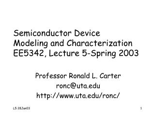
HeterojunctionElectrostatics Eo qfp EC,p qfn DEC EC,n EF,p EF,n EV,p EV,n DEV xp -xn 0
Poisson’s Equation Ex x -xn xp
Final Exam • Review a paper on “Device Parameter Extraction”. • Paper to be reviewed will be posted Monday, May 5, 2003 • Comment on Device Physics used. • Critique the extraction procedures • Assumptions • Consistency of method w.r.t. assumptions • One page solution due 11 AM, Thur., May 8
References • Fujiang Lin, et al, “Extraction Of VBIC Model for SiGe HBTs Made Easy by Going Through Gummel-Poon Model”, from http://eesof.tm.agilent.com/pdf/VBIC_Model_Extraction.pdf • http://www.fht-esslingen.de/institute/iafgp/neu/VBIC/ • Avanti Star-spice User Manual, 04, 2001. • AffirmaSpectre Circuit Simulator Device Model Equations • Zweidinger, D.T.; Fox, R.M., et al, “Equivalent circuit modeling of static substrate thermal coupling using VCVS representation”, Solid-State Circuits, IEEE Journal of , Volume: 2 Issue: 9 , Sept. 2002, Page(s): 1198 -1206