Download
1 / 8
80 likes | 102 Vues
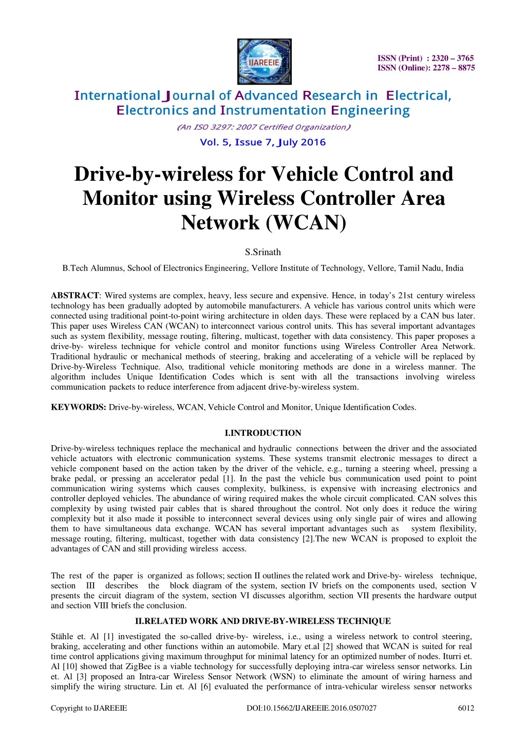
Wired systems are complex, heavy, less secure and expensive. Hence, in today’s 21st century wireless<br>technology has been gradually adopted by automobile manufacturers. A vehicle has various control units which were<br>connected using traditional point-to-point wiring architecture in olden days. These were replaced by a CAN bus later.<br>This paper uses Wireless CAN (WCAN) to interconnect various control units. This has several important advantages<br>such as system flexibility, message routing, filtering, multicast, together with data consistency. This paper proposes a<br>drive-by- wireless technique for vehicle control and monitor functions using Wireless Controller Area Network.<br>Traditional hydraulic or mechanical methods of steering, braking and accelerating of a vehicle will be replaced by<br>Drive-by-Wireless Technique. Also, traditional vehicle monitoring methods are done in a wireless manner. The<br>algorithm includes Unique Identification Codes which is sent with all the transactions involving wireless communication packets to reduce interference from adjacent drive-by-wireless system.

E N D
ISSN (Print) : 2320 – 3765 ISSN (Online): 2278 – 8875 International J ournal of Advanced R esearch in E lectrical, E lectronics and Instrumentation E ngineering ( An I SO 3297: 2007 Certified Org anization) Vol. 5, I ssue 7, J uly 2016 Drive-by-wireless for Vehicle Control and Monitor using Wireless Controller Area Network (WCAN) S.Srinath B.Tech Alumnus, School of Electronics Engineering, Vellore Institute of Technology, Vellore, Tamil Nadu, India ABSTRACT:Wired systems are complex, heavy, less secure and expensive. Hence, in today’s 21st century wireless technology has been gradually adopted by automobile manufacturers. A vehicle has various control units which were connected using traditional point-to-point wiring architecture in olden days. These were replaced by a CAN bus later. This paper uses Wireless CAN (WCAN) to interconnect various control units. This has several important advantages such as system flexibility, message routing, filtering, multicast, together with data consistency. This paper proposes a drive-by- wireless technique for vehicle control and monitor functions using Wireless Controller Area Network. Traditional hydraulic or mechanical methods of steering, braking and accelerating of a vehicle will be replaced by Drive-by-Wireless Technique. Also, traditional vehicle monitoring methods are done in a wireless manner. The algorithm includes Unique Identification Codes which is sent with all the transactions involving wireless communication packets to reduce interference from adjacent drive-by-wireless system. KEYWORDS: Drive-by-wireless, WCAN, Vehicle Control and Monitor, Unique Identification Codes. I.INTRODUCTION Drive-by-wireless techniques replace the mechanical and hydraulic connections between the driver and the associated vehicle actuators with electronic communication systems. These systems transmit electronic messages to direct a vehicle component based on the action taken by the driver of the vehicle, e.g., turning a steering wheel, pressing a brake pedal, or pressing an accelerator pedal [1]. In the past the vehicle bus communication used point to point communication wiring systems which causes complexity, bulkiness, is expensive with increasing electronics and controller deployed vehicles. The abundance of wiring required makes the whole circuit complicated. CAN solves this complexity by using twisted pair cables that is shared throughout the control. Not only does it reduce the wiring complexity but it also made it possible to interconnect several devices using only single pair of wires and allowing them to have simultaneous data exchange. WCAN has several important advantages such as system flexibility, message routing, filtering, multicast, together with data consistency [2].The new WCAN is proposed to exploit the advantages of CAN and still providing wireless access. The rest of the paper is organized as follows; section II outlines the related work and Drive-by- wireless technique, section III describes the block diagram of the system, section IV briefs on the components used, section V presents the circuit diagram of the system, section VI discusses algorithm, section VII presents the hardware output and section VIII briefs the conclusion. II.RELATED WORK AND DRIVE-BY-WIRELESS TECHNIQUE Stähle et. Al [1] investigated the so-called drive-by- wireless, i.e., using a wireless network to control steering, braking, accelerating and other functions within an automobile. Mary et.al [2] showed that WCAN is suited for real time control applications giving maximum throughput for minimal latency for an optimized number of nodes. Iturri et. Al [10] showed that ZigBee is a viable technology for successfully deploying intra-car wireless sensor networks. Lin et. Al [3] proposed an Intra-car Wireless Sensor Network (WSN) to eliminate the amount of wiring harness and simplify the wiring structure. Lin et. Al [6] evaluated the performance of intra-vehicular wireless sensor networks Copyright to IJAREEIE DOI:10.15662/IJAREEIE.2016.0507027 6012
ISSN (Print) : 2320 – 3765 ISSN (Online): 2278 – 8875 International J ournal of Advanced R esearch in E lectrical, E lectronics and Instrumentation E ngineering ( An I SO 3297: 2007 Certified Org anization) Vol. 5, I ssue 7, J uly 2016 (IVWSNs) under interference from WiFi and Bluetooth devices. Torbitt et. Al [7] analysed the surface wave hypothesis at different frequencies in intra-vehicular environments. Ahmed et. Al [8] investigated the issues around replacing the current wired data links between electrical control units (ECU) and sensors/switches in a vehicle, with wireless links. Lin et. Al [9] proposed a new wireless technology known as Bluetooth Low Energy (BLE) and outlined a new architecture for IVWSN. This paper proposes Drive-by- wireless technique using WCAN. Drive-by-wire technology in the automotive industry is the use of electrical or electro-mechanical systems for performing vehicle functions traditionally achieved by mechanical linkages. This technology replaces the traditional mechanical control systems with electronic control systems using electromechanical actuators and human-machine interfaces such as pedal and steering feel emulators. The Drive-by-wire system used point to point communication wiring systems as shown in Figure 1. This causes complexity, heaviness and is expensive. Figure 1. Existing System The Drive-by-wireless system ensures less weight, safety and comfort. The position of the sensor, motor and the wheel for the proposed Drive-by-wireless system is shown in Figure 2. Figure 2. Drive-by-wireless System III.BLOCK DIAGRAM OF THE PROPOSED SYSTEM The block diagram of the system is presented in Figure 3. The system has four microcontroller units and ZigBee over 802.15.4 protocol is used for wireless communication. The Steering, Brake, Accelerator sensors are associated with the Copyright to IJAREEIE DOI:10.15662/IJAREEIE.2016.0507027 6013
ISSN (Print) : 2320 – 3765 ISSN (Online): 2278 – 8875 International J ournal of Advanced R esearch in E lectrical, E lectronics and Instrumentation E ngineering ( An I SO 3297: 2007 Certified Org anization) Vol. 5, I ssue 7, J uly 2016 Engine Control Unit. The Dashboard unit contains the LCD, the D.C. Motor unit contains a D.C. motor with a motor drive and a temperature sensor. Finally, the Servo Motor Unit contains a Servo Motor and a level sensor. Figure 3. Block Diagram IV.COMPONENTS DESCRIPTION PIC18F45K22 is the microcontroller used in the project. Circular potentiometers are used for Brake- Acceleration and Steering. Servo Motor and a level sensor is used for the Servo Motor Unit and DC Motor unit contains a D.C. motor with a motor drive and a temperature sensor. LCD Display is used for displaying the engine temperature and fuel levels. A. PIC18F45K22 - PIC18(L)F45K22 has 32k program memory, 1536 bytes of SRAM and 256bytes of EEPROM. It has three 8-bit timers and four 16-bit timers. All of the devices in the PIC18(L)F2X/4XK22 family offer ten different oscillator options, allowing users a wide range of choices in developing application hardware. These include: • Four Crystal modes, using crystals or ceramic resonators • Two External Clock modes, offering the option of using two pins (oscillator input and a divide-by-4 clock output) or one pin (oscillator input, with the second pin reassigned as general I/O) • Two External RC Oscillator modes with the same pin options as the External Clock modes • An internal oscillator block which contains a 16 MHz HFINTOSC oscillator and a 31 kHz LFINTOSC oscillator, which together provide eight user selectable clock frequencies, from 31 kHz to 16 MHz. This option frees the two oscillator pins for use as additional general purpose I/O. • A Phase Lock Loop (PLL) frequency multiplier, available to both external and internal oscillator modes, which allows clock speeds of up to 64 MHz. Used with the internal oscillator, the PLL gives users a complete selection of clock speeds, from 31 kHz to 64 MHz – all without using an external crystal or clock circuit. B. Potentiometers - A potentiometer is a three terminal resistor with a sliding contact forms an adjustable voltage divider and only two terminals are used one end and the wiper acts as a variable resistor or rheostat. Electric potential is measured by potentiometer device. C. LCD Display - The HD44780U dot-matrix liquid crystal display controller and driver LSI displays alpha-numerics, Japanese kana characters, and symbols. It can be configured to drive a dot-matrix liquid crystal display under the control of a 4- or 8-bit microprocessor. Since all the functions such as display RAM, character generator, and liquid crystal driver, required for driving a dot-matrix liquid crystal display are internally provided on one chip, a minimal system can be interfaced with this controller/driver. A single HD44780U can display up to one 8-character line or two 8-character lines. The HD44780U has pin function compatibility with the HD44780S which allows the user to easily replace an LCD-II with an HD44780U. The HD44780U character generator ROM is extended to generate 208 5x8 dot Copyright to IJAREEIE DOI:10.15662/IJAREEIE.2016.0507027 6014
ISSN (Print) : 2320 – 3765 ISSN (Online): 2278 – 8875 International J ournal of Advanced R esearch in E lectrical, E lectronics and Instrumentation E ngineering ( An I SO 3297: 2007 Certified Org anization) Vol. 5, I ssue 7, J uly 2016 character fonts and 32 5 x10 dot character fonts for a total of 240 different character fonts. The low power supply (2.7V to 5.5V) of the HD44780U is suitable for any portable battery-driven product requiring low power dissipation. D. DC Motor - A DC motor has a two wire connection. All drive power is supplied over these wires. Most DC motors are pretty fast of about 5000 rpm. The DC motor speed is controlled by a technique called pulse width modulation or PWM. E. Servo Motor - The function of the servo is to receive a control signal that represents a desired output position of the servo shaft, and apply power to its DC motor until the shaft turns to that position. It uses position sensing device to rotate the shaft. The shaft can turn a maximum of 200 degree so back and forth. F. Pressure Sensor - The MPX5010/MPXV5010G series piezoresistive transducers are state-of the-art monolithic silicon pressure sensors designed for a wide range of applications, but particularly those employing a microcontroller or microprocessor with A/D inputs. This transducer combines advanced micromachining techniques, thin-film metallization, and bipolar processing to provide an accurate, high level analog output signal that is proportional to the applied pressure. It’s features are • 5.0% Maximum Error over 0° to 85°C • Ideally Suited for Microprocessor or Microcontroller-Based Systems • Durable Epoxy Unibody and Thermoplastic (PPS) Surface Mount Package • Temperature Compensated over .40° to +125°C G. Temperature Sensor - The LM35 series are precision integrated-circuit temperature sensors, whose output voltage is linearly proportional to the Celsius (Centigrade) temperature. The LM35 thus has an advantage over linear temperature sensors calibrated in ° Kelvin, as the user is not required to subtract a large constant voltage from its output to obtain convenient Centigrade scaling. The LM35 does not require any external calibration or trimming to provide typical accuracies of ±1⁄4°C at room temperature and ±3⁄4° cover a full −55 to +150°C temperature range. Low cost is assured by trimming and calibration at the wafer level. The LM35’s low output impedance, linear output, and precise inherent calibration make interfacing to readout or control circuitry especially easy. It can be used with single power supplies, or with plus and minus supplies. As it draws only 60 μA from its supply, it has very low self-heating, less than 0.1°C in still air. The LM35 is rated to operate over a −55° to +150°C temperature range, while the LM35C is rated for a −40° to +110°C range (−10° with improved accuracy). The LM35 series is available packaged in hermetic TO-46 transistor packages, while the LM35C, LM35CA, and LM35D are also available in the plastic TO-92 transistor package. The LM35D is also available in an 8-lead surface mount small outline package and a plastic TO-220 package. H. CAN MCP2515 - It is a Stand-Alone CAN Controller with SPI Interface, 18 pin I.C. • Implements CAN V2.0B at 1 Mb/s: 0 – 8 byte length in the data field, Standard and extended data and remote frames • Receive Buffers, Masks and Filters: Two receive buffers with prioritized message Storage, Six 29-bit filters and Two 29-bit masks • Data Byte Filtering on the First Two Data Bytes (applies to standard data frames) • Three Transmit Buffers with Prioritization and Abort Features • High-Speed SPI Interface (10 MHz): SPI modes 0,0 and 1,1 • One-Shot mode Ensures Message Transmission is Attempted Only One Time • Clock-Out-Pin with Programmable Prescaler: Can be used as a clock source for other device(s) • Start-of-Frame Signal is Available for Monitoring the SOF Signal: Can be used for time-slot-based protocols and/or bus diagnostics to detect early bus degradation V. CIRCUIT DIAGRAM The system comprises of four control units which communicate with each other using Zigbee over 802.15.4 protocol. The four modules are Engine Control Unit, D.C. Motor Unit, Servo Motor Unit and the Dashboard Unit. The input 220V A.C. power supply is converted to 12V D.C. by an adapter. Various units in the modules require only 5V D.C and 3.3 V D.C. power supply. Hence a regulator is used for this purpose. The PIC18F45K22 microcontroller is a 40 pin I.C. There are 5 ports. Port A, B, C and D have 8 pins each while Port E has 3 pins. The remaining 5 pins are used for Copyright to IJAREEIE DOI:10.15662/IJAREEIE.2016.0507027 6015
ISSN (Print) : 2320 – 3765 ISSN (Online): 2278 – 8875 International J ournal of Advanced R esearch in E lectrical, E lectronics and Instrumentation E ngineering ( An I SO 3297: 2007 Certified Org anization) Vol. 5, I ssue 7, J uly 2016 MCLR, VDD and Ground. The ICSP (In Circuit Serial Programmer) is a 5 pin device which is used by PitKit 3 to dump the program from the computer to the microcontroller. Pin 1 of the ICSP is connected to a high voltage to erase any previous programs, Pin 2 is the clock, Pin 3 is the data, Pin 4 is connected to Ground while Pin 5 is connected to VDD. The Dashboard Module circuit diagram is shown in Figure 4. It consists of a 16x2 LCD display. Figure 4. The Dashboard Module SP1 and SP2 of the PIC18F45K22 are pins A5, C3, C4, C5 and A6, C3, C4, C5 respectively. A5 and A6 are the Enable Pin, C3 is the clock, C4 is the Data Input and C5 is the Data Output. UART1 and UART2 are pins 25, 26 and 29, 30 respectively. 25 and 29 are for transmission while 26 and 30 are for reception. In CAN, CANL is for transmission and CANH is for reception. In Zigbee Pin 2 is for transmission and Pin 3 is for reception. As shown in Figure 5, Pin 1 of Port C is used for the motor drive circuit while Pin 1 of Port A is used for the pressure sensor. Figure 5. The D.C. Motor Module As shown in Figure 6, Pin 1 of Port C is connected to the servo motor while Pin 1 of Port A is connected to the temperature sensor. Figure 6. The Servo Motor Module Copyright to IJAREEIE DOI:10.15662/IJAREEIE.2016.0507027 6016
ISSN (Print) : 2320 – 3765 ISSN (Online): 2278 – 8875 International J ournal of Advanced R esearch in E lectrical, E lectronics and Instrumentation E ngineering ( An I SO 3297: 2007 Certified Org anization) Vol. 5, I ssue 7, J uly 2016 In Figure 7, the first three pins of Port A are connected to the Accelerator Sensor, Brake Sensor and Steering Sensor respectively. Figure 7. The Engine Control Module VI. ALGORITHM Some of the pseudo-codes for various control units are shown below. MPLAB IDE is the development platform used for coding. tostring(adcvalue1, dispstring); cantx('A'); cantx(dispstring[0]); cantx(dispstring[1]); cantx(dispstring[2]); cantx(dispstring[3]); cantx(dispstring[4]); In the above pseudo-code, the data obtained by various sensor units in the Engine Control Unit are converted into string and transmitted using CAN. Before transmission identification characteristics like ‘A’, ‘B’, etc are also transmitted. if(adcvalue1 > adcvalue2) { accelerator = adcvalue1 - adcvalue2; } else { accelerator = 0 } The above conditions are followed in the D.C. motor unit. adcvalue1 = map(adcvalue1 , 0, 1023, 1, 150); temp = adcvalue1; angle1_act = temp; angle11 = angle1_act/10; datareceivedbit = 0; The above condition is followed in the Servo motor unit. The ADC values obtained by the engine control module steering sensor is mapped as 1 for 0 and 150 for 1023 and the servo motor is driven. VII. HARDWARE OUTPUT The Servo Motor Module is shown in Figure 8. It consists of a Servo Motor and a Level Sensor. The Level Sensor that acquire the data need to be interfaced with the microcontroller. This would ensure that the output of the sensor is in a format recognized and understood by the microcontroller. Thus we interface the ADC. Next, the data acquired by the ADCs needs to be passed on from the microcontroller to the Tarang Module through WCAN using serial Copyright to IJAREEIE DOI:10.15662/IJAREEIE.2016.0507027 6017
ISSN (Print) : 2320 – 3765 ISSN (Online): 2278 – 8875 International J ournal of Advanced R esearch in E lectrical, E lectronics and Instrumentation E ngineering ( An I SO 3297: 2007 Certified Org anization) Vol. 5, I ssue 7, J uly 2016 communication. Hence we do serial communication initialization and set baud rate at 9600bps. When the Steering Sensor of the ECU is rotated the Servo Motor moves towards left or right direction accordingly. Figure 8. The Servo Motor Module includes Servo Motor and Level Sensor The Engine Control Module (ECU) is shown in Figure 9. It consists of three sensors namely the accelerator sensor, the brake sensor and the steering sensor. The steering sensor controls the Servo Motor and the other two sensors controls the DC Motor. Figure 9. The Engine Control Module which includes 3 ADC sensors, WCAN and Tarang RF Module The Dashboard Module is shown in Figure 10. It consists of a 16x2 LCD display. LCD interfacing is done for the LCD used in the dashboard module. The LCD displays the output of the Level Sensor and the Temperature Sensor. Figure 10. The Dashboard Module which includes the 16x2 LCD display The D.C. Motor Module is shown in Figure 11. It consists of a D.C. Motor and a Temperature Sensor. When the Accelerator Sensor of the ECU is rotated the DC Motor begins to rotate. Similarly when the brake sensor of the ECU is rotated the DC Motor begins to stop. Copyright to IJAREEIE DOI:10.15662/IJAREEIE.2016.0507027 6018
ISSN (Print) : 2320 – 3765 ISSN (Online): 2278 – 8875 International J ournal of Advanced R esearch in E lectrical, E lectronics and Instrumentation E ngineering ( An I SO 3297: 2007 Certified Org anization) Vol. 5, I ssue 7, J uly 2016 Figure 11. The D.C. Motor Module includes the DC Motor and the Temperature Sensor VIII. CONCLUSION With the above experiments, that the concept of drive-by-wireless is feasible. Error detection is also made easier using this technique. Safety of the automobile system is also guaranteed. Complexity, bulkiness and heaviness of the system is reduced. The system is also made less expensive. REFERENCES [1] Hauke St¨ahle, Kai Huang, Alois Knoll, “Drive-by-Wireless with the eCar Demonstrator”, Proceedings of the 4th ACM SIGBED International Workshop on Design, Modeling, and Evaluation of Cyber-Physical Systems. ACM, pp. 1-4, 2014. Mary, Gerardine Immaculate, Zachariah C. Alex, and LawrenceJenkins., "REAL TIME ANALYSIS OF WIRELESS CONTROLLER AREA NETWORK.", ICTACT JOURNAL ON COMMUNICATION TECHNOLOGY, Volume.05, Issue. 03, pp.951-958, September 2014. J.-R. Lin, T. Talty, and O. Tonguz, “Feasibility of safety applications based on intra-car wireless sensor networks: A case study”,in Vehicular Technology Conference (VTC Fall), 2011 IEEE, pp. 1–5, 2011. C. Buckl, A. Camek, G. Kainz, C. Simon, L. Mercep, H. Staehle, and A. Knoll, “The software car: Building ict architectures for future electric vehicles”, in Electric Vehicle Conference (IEVC), 2012 IEEE International, pp. 1–8, March 2012. M. Eder and A. Knoll, “Design of an experimental platform for an x-by-wire car with four-wheel steering”, in Automation Science and Engineering (CASE), 2010 IEEE Conference on, pp. 656–661, 2010. Lin, Jiun-Ren, Timothy Talty, and Ozan K. Tonguz, "An empirical performance study of Intra-vehicular Wireless Sensor Networks under WiFi and Bluetooth interference", In Global Communications Conference (GLOBECOM), 2013 IEEE, pp. 581-586, 2013. Torbitt, C., Tomsic, K., Venkataraman, J., Tsouri, G. R., Laifenfeld, M., & Dziatczak, M.,“Investigation of waveguide effects in intra-vehicular environments”, In Antennas and Propagation Society International Symposium (APSURSI), pp. 599-600, July,2014. Ahmed, Mohiuddin, Cem U. Saraydar, Tamer ElBatt, Jijun Yin, Timothy Talty, and Michael Ames, "Intra-vehicular wireless networks", In Globecom Workshops, 2007 IEEE, pp. 1-9, 2007. Lin, Jiun-Ren, Timothy Talty, and Ozan K. Tonguz. "On the potential of bluetooth low energy technology for vehicular applications." Communications Magazine,IEEE , Vol.53, Issue. 1, pp. 267-275, 2015. [10]Iturri, Peio Lopez, Erik Aguirre, Leire Azpilicueta, Uxue Garate, and Francisco Falcone, "ZigBee Radio Channel Analysis in a Complex Vehicular Environment [Wireless Corner]", Antennas and Propagation Magazine, IEEE, Vol.56, no. 4, pp.232-245, 2014. [11]Deng, Han, Jia Li, Liuqing Yang, and Timothy Talty, "Intra- vehicle UWB MIMO channel capacity", In Wireless Communications and Networking Conference Workshops (WCNCW), 2012 IEEE, pp. 393-397, 2012. [2] [3] [4] [5] [6] [7] [8] [9] BIOGRAPHY S.Srinathpassed 10th C.B.S.E. Board with a mark of 475/500(95%) in 2009 and 12th C.B.S.E. Board from D.A.V. Boys Senior Secondary School, Gopalpuram, Chennai, India with a mark of 458/500(91.6%) in 2011 .He graduated with B.Tech, ECE, from School of Electronics Engineering in Vellore Institute of Technology, Vellore, India with a C.G.P.A. of 8.39/10 in May 2015. Copyright to IJAREEIE DOI:10.15662/IJAREEIE.2016.0507027 6019