Download

1 / 19
290 likes | 722 Vues
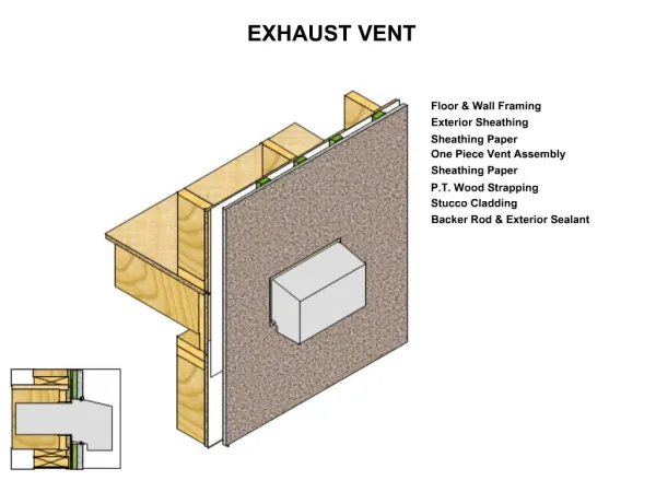
Local Exhaust Hoods. Local Exhaust Hoods. Introduction: Designed to capture and remove harmful emissions from various processes prior to their escape into the workplace. Hood is the place where the process emission enters the exhaust system.

E N D
Local Exhaust Hoods Introduction: • Designed to capture and remove harmful emissions from various processes prior to their escape into the workplace. • Hood is the place where the process emission enters the exhaust system. • Main function of the hood is to capture the contaminants and transport them into the hood. • An air field is created in the hood for the above function. • Fig.3-1, page 3-3, ACGIH manual shows nomenclature associated with local exhaust hoods. Local Exhaust Hoods
Contaminant Characteristics • Inertial effects: movement with respect to air depends on their inertia. • Effective specific gravity: specific gravity affects the density which in turn effects the motion of particles with the air. • Wake effects: A turbulent wake is created due to air flow around an object. Local Exhaust Hoods
Hood Types Enclosing hoods: • Hoods which completely or partially enclose the contaminant generation point these are preferred wherever the process configuration and operation will permit. Exterior hoods: • Hoods located adjacent to the source. Examples are slots along the edge of the tank or a rectangular opening on a welding table. Criteria for hood selection: - Physical characteristics of the equipment. - Contaminant generation mechanism. - Equipment surface. Fig 3-3, page 3-5, ACGIH manual shows different types of hoods. Local Exhaust Hoods
Factors Affecting Hood Design • Capture velocity • Hood flow rate determination • Effect of flanges and baffles • Air distribution • Rectangular and round hoods • Worker position effect Local Exhaust Hoods
Capture Velocity • It is the minimum hood induced air velocity necessary to capture and convey the contaminants into the hood • It is the result of hood air flow rate and hood configuration Factors affecting selection of values of capture velocity • Lower end of range- • Room air currents minimal or favorable to capture • Contaminants of low toxicity or of nuisance value only • Intermittent, low production • Large hood – large air mass in motion • Upper end of range- • Distributing room air currents • Contaminants of high toxicity • High production, heavy use • Small hood - local control only Local Exhaust Hoods
Hood Flow Rate Determination • For an enclosure capture velocity at the enclosed opening is the exhaust flow rate divided by opening area • The capture velocity at a given point in front of the exterior hood will be established by the hood air flow through the geometric surface which contains the point • For a theoretical unbounded point suction source Q = v * a = v * 4 * π * x2 = 12.57 * v * x2 Where Q = air flow into suction point, cfm V = velocity at distance X, fpm A = 4 * Π * X2 = area of sphere, ft2 X = radius of sphere, ft Local Exhaust Hoods
Hood Flow Rate Determination • For an unbounded line source Q = v *2 * π * x * l = 6.28 * v * x * l Where L = length of line source, ft • In general the equation used is Q = v * (10 * x2 + a) Where Q = air flow, cfm V = center line velocity at X distance from hood, fpm X = distance outward along axis of flow in ft A = area of hood opening, ft2 D = diameter of round hoods or side of essentially square hoods, ft Local Exhaust Hoods
Effect Of Flanges And Baffles Flange: • It is a surface at and parallel to the hood face which provides a barrier to unwanted air flow from behind the hood. Baffle: • It is a surface which provides a barrier to unwanted air flow from the front or sides of the hood.. Functions of flanges and baffles: • Reducing the flow area which in turn reduces the flow rate required to achieve a given capture velocity. • Flow rate is approximately reduced by 25% in practice. • For most applications the flange width should be equal to the square root of the hood area (√ A ). Local Exhaust Hoods
Air Distribution • Slots are generally used for uniform air distribution. • Hoods with an opening width - to - length ratio of 0.2 or less are slot hoods. • They provide uniform exhaust air flow and adequate capture velocity over a finite length of contaminant generation. • Slot velocity does not contribute toward capture velocity. • Slot length and exhaust volume effect the capture velocity. Local Exhaust Hoods
Rectangular And Round Hoods • Air distribution for rectangular and round hoods is achieved by air flow within the hood rather than by pressure drop as for the slot hood. • The area of the hood changes with the shape of the hood. • The effect of slot is different in both cases. • Different kind of distribution techniques can be used. Local Exhaust Hoods
Worker Position Effect • Workers position considerably effects the exposure. • Local exhaust ventilation is designed to be near the point of contaminant generation. • The worker should be such oriented that contaminants flow with air flow. • The contaminants should not enter the breathing zone. Local Exhaust Hoods
Hood Losses • Entry losses occur due to formation of venacontracta at the entrance of duct. • The hood entry loss represents the energy necessary to overcome the loss as the air enters the duct. • The losses increase with increase in flow area. • Hoods with two or more points of loss are compound hoods. The basic equations used are (for simple hood) SPh = hed + VPd Where SPh = hood static pressure, “wg hed = entry loss transition (Fh * VPd ) VPd = duct velocity pressure Local Exhaust Hoods
Hood Losses For compound hoods: SPh = (FS) (VPS) + (FD) (VPD) + VPD This is when duct velocity is greater than slot velocity. Where: SPh = hood static pressure, “wg FS = entry loss factor for slot VPS = slot velocity pressure, “wg FD = entry loss factor for duct VPD = duct velocity pressure, “wg Local Exhaust Hoods
Minimum Duct Velocity • Depends on type of material being transported. • Used to calculate duct velocity pressure and hood losses. Factors affecting minimum duct velocity: • Plugging or closing of branch. • Damage to ducts (e.G. Denting). • Leakage of ducts. • Corrosion or erosion of fan wheel. • Slipping of fan drive belt. • Velocities should be able to pick up dust particles which may have settled due to improper operation. Table 3-2, page 3-19, ACGIH manual shows values of typical duct velocities. Local Exhaust Hoods
Special Hood Requirements Ventilation of high toxicity and radioactive processes: • Extraordinarily effective control methods are to be used. • Knowledge of hazards and adequate maintenance required that includes monitoring. • Enclosing type of hood preferred. • Replacement air should be introduced at low velocity and in a direction so that it does not produce disruptive cross drafts at the hood opening. Laboratory operations: • Glove boxes should be used. • For low activity radioactive laboratory work, a laboratory fume hood may be acceptable. Local Exhaust Hoods
Push - Pull Ventilation • It is a kind of variation to exterior hoods. • A jet of air is pushed across contaminant source into the flow field of hood. • Contaminant control is primarily achieved by the jet. • Exhaust receives the jet and removes it. • Advantage is that jet can travel greater distance in a controlled manner. • The system is harmful if not properly designed, installed or operated. Local Exhaust Hoods
Hot Process • Designed differently than normal hoods. • Thermal draft created due to convection and conduction. • Draft causes upward air current with high velocities. Equation used to find flow rate for rectangular and circular high canopy hoods Dc = 0.5 * xc0.88 Where: DC = column diameter at hood face. XC = y +z = the distance from the hypothetical point source to the hood face, ft Y = distance from the process surface to the hood face, ft Z = distance from the process surface to the hypothetical point source, ft Z = (2 * DS)1.138 Where: DS = diameter of hot source, ft Local Exhaust Hoods
Hot Process Qt = Vf * Ac + Vr * (Af - Ac) Where: Qt = total volume entering hood, cfm Vf = velocity of hot air column at the hood face, fpm Ac = area of the hot air column at the hood face, ft2 Vr = the required velocity through the remaining hood area, fpm Af = total area of hood face, ft2 For low canopy hoods: Qt = 4.7 * ( Df)233 * (Δt)0.42 Where: Qt = total hood air flow, cfm Df = diameter of hood, ft Δt = difference between temperature of the hot source, and the ambient, F. Local Exhaust Hoods