Download

1 / 7
80 likes | 427 Vues
Thermal Cycling Tests of Dummy Modules Setup Pre-cycling resistance measurements IZM module results Alenia module underway Setup Modules built with CERN Flex V.2 and bare dummy module. Used Ecobond glue under MCC, pigtail bonding field, and 4 corners.

E N D
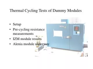
Thermal Cycling Tests of Dummy Modules • Setup • Pre-cycling resistance measurements • IZM module results • Alenia module underway
Setup • Modules built with CERN Flex V.2 and bare dummy module. • Used Ecobond glue under MCC, pigtail bonding field, and 4 corners. • Modules used for FE wirebonding tests prior to thermal cycling • First cycled modules unconstrained, then attached to sector using CGL and UV-cure tacks on 4 corners. • Cycled 21oC to –35oC in environmental chamber. • Monitored module temperature and chain resistance in real time
Setup (cont.) Only 4 columns monitored in real time during cycling W W All columns measured on probe station before and after
Column Resistances (before cycling) Bad chip Alenia IZM
IZM Module results • No change after 2 cycles of unconstrained module • No change DURING 19 cycles of module on sector • Open columns detected AFTER overnight storage at 21oC On bad chip, all columns were open prior to tests & chip fell off after removing module from sector. Solder bumps left ½ on chip ½ on sensor. RED = location of open column 32/270 columns failed
Possible Explanation UV Tack UV Tack • Results are consistent with differential movement of dummy chips and dummy sensor. • For example, assume sensor doesn’t move under cooldown(probably not correct, just example), then contraction of each chip is about (2.5x10⁻⁶) x(either 3.7 or 5.5x10³ microns)x56=0.5-0.8 microns. • Worst case is corners of chip, but we only measure columns. • Approximate strain is (0.5-0.8)/(20) or 2.5-3.8%.. Solder stress vs strain becomes non-linear for strains above about 1%. • Creep rupture is possible explanation for failure after sitting. Carbon-carbon on sector CGL
Alenia Module Tests Underway • 3 Cycles to –35o unconstrained • 3 Cycles to –35o mounted on sector • Time at –35o 30-40 minutes/cycle • Let sit for a day • No failures yet • Tests continuing