Download
1 / 28
280 likes | 290 Vues
Explore the EZ Series Metering Pumps in the EZ11 Manual PDF by Walchem. Discover efficient and precise pumping solutions for various industrial applications.

E N D
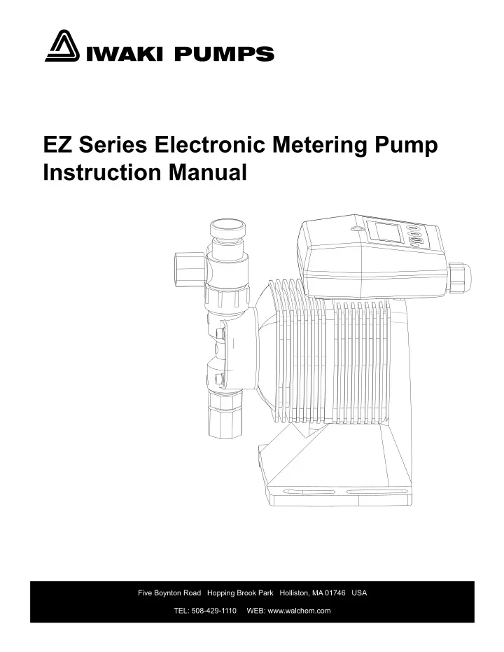
IWAKI PUMPS EZ Series Electronic Metering Pump Instruction Manual Five Boynton Road Hopping Brook Park Holliston, MA 01746 USA TEL: 508-429-1110 WEB: www.walchem.com
Notice © 2021 WALCHEM, Iwaki America Inc. (hereinafter “Walchem”) Five Boynton Road, Holliston, MA 01746 USA tel (508) 429-1110 fax (508) 429-7433 All Rights Reserved Printed in USA Proprietary Material The information and descriptions contained herein are the property of WALCHEM. Such information and descriptions may not be copied or reproduced by any means, or disseminated or distributed without the express prior written permission of WALCHEM. This document is for information purposes only and is subject to change without notice. Statement of Limited Warranty WALCHEM warrants equipment of its manufacture and bearing its identification to be free from defects in workmanship and material for a period of two years from date of delivery from the factory or authorized distributor under normal use and service and otherwise when such equipment is used in accordance with instructions furnished by WALCHEM and for the purposes disclosed in writing at the time purchased, if any. WALCHEM’s liability under this warranty shall be limited to replacement or repair, F.O.B. Holliston, MA U.S.A. of any defective equipment or part which, having been returned to WALCHEM, transportation charges prepaid, has been inspected and determined by WALCHEM to be defective. THIS WARRANTY IS IN LIEU OF ANY OTHER WARRANTY, EITHER EXPRESS OR IMPLIED, AS TO DESCRIPTION, QUALITY, MERCHANT-ABILITY, FITNESS FOR ANY PARTICULAR PURPOSE OR USE, OR ANY OTHER MATTER. P/N E00159.P February 2021
TABLE OF CONTENTS Thank you for choosing a Walchem EZ Series metering pump. This instruction manual deals with the correct installation, operation, maintenance and troubleshooting procedures for the EZ metering pumps. Please read through it carefully to ensure the optimum performance, safety and service of your pump. Contents 1.0 INTRODUCTION ..................................................................................... 1 1.1 Safety and Caution Notes ...............................................................................................................................1 1.2 Principle of Operation .....................................................................................................................................1 1.3 Model Code ......................................................................................................................................................2 1.4 Specifications ..................................................................................................................................................2 1.4.1 Electrical................................................................................................................................................2 1.4.2 Operating Conditions...........................................................................................................................2 1.4.3 Capacity/Pressure Rating ....................................................................................................................3 1.4.4 Adjustment Range................................................................................................................................3 1.4.5 Materials of Construction ....................................................................................................................3 1.5 Dimensions ......................................................................................................................................................4 2.0 INSTALLATION ....................................................................................... 6 2.1 Unpacking ........................................................................................................................................................6 2.2 Location ...........................................................................................................................................................6 2.3 Supply Tubing ..................................................................................................................................................7 2.4 Discharge Tubing ............................................................................................................................................8 2.5 Installing Injection/BackPressure Valve ........................................................................................................8 2.6 Interlocking Pump ...........................................................................................................................................9 2.7 Electrical ..........................................................................................................................................................9 3.0 OPERATION ............................................................................................ 9 3.1 Priming .............................................................................................................................................................9 3.2 Adjustment and Control .................................................................................................................................10 3.3 Calibration ........................................................................................................................................................10 3.4 STOP Function .................................................................................................................................................10 3.5 AC Power Interruption ....................................................................................................................................11 3.6 Auto Degassing Valve Operation ...................................................................................................................11 3.7 MultiFunction Valve Operation .......................................................................................................................12 4.0 MAINTENANCE......................................................................................13 4.1 Diaphragm Replacement ................................................................................................................................13 4.2 Valve Replacement ..........................................................................................................................................13 4.3 Tubing ...............................................................................................................................................................13 5.0 EXPLODED VIEW & PARTS GUIDE......................................................14 6.0 TROUBLESHOOTING............................................................................25 7.0 SERVICE POLICY...................................................................................25
1.0 INTRODUCTION 1.1 Safety and Caution Notes Always wear protective clothing, eye protection and gloves before working on or near a metering pump. Follow all recommendations of the supplier of the solution being pumped. Refer to the MSDS from the solution supplier for additional precautions. Walchem EZ Series metering pumps should be installed where ambient temperatures do not exceed 122°F (50°C) or do not fall below 32°F (0°C). Pumps should always be shielded from direct exposure to the elements. Black UV resistant tubing should be used if the tubing is exposed to strong UV radiation (sunlight/lamps). WARNING Risk of electrical shock! This pump is supplied with a grounding conductor and grounding-type attachment plug. To reduce the risk of electrical shock, be certain that it is connected only to a properly grounded, grounding type receptacle with ratings conforming to the data on the pump data plate. Prior to performing any maintenance on a pump, disconnect the pump from the electrical power source. Plumbing Precautions All tubing must be securely attached to the fittings prior to starting the pump (see Section 2.3). Only use Walchem tubing with your pump. Tubing should be shielded to prevent possible injury in case of rupture or damage. UV resistant tubing should be used if the tubing is exposed to UV light. Always adhere to local plumbing codes and requirements. Be sure that the installation does not constitute a cross connection. Walchem is not responsible for improper installations. Prior to performing any maintenance on a pump, depressurize the discharge tubing. In flooded suction, pumping downhill, or pumping into little or no system pressure installations, a back pressure/anti-syphon device must be installed to prevent over-pumping or siphoning. Contact your Walchem distributor for additional information. Solution Compatibility CAUTION! This pump has been evaluated for use with water only. The suitability of this pump for use with liquids other than water (such as acids or alkalines) is the responsibility of the user. For liquids other than water, select the best-suited liquid end material combination using a chemical compatibility chart. 1.2 Principle of Operation The EZ series electronic metering pumps consist of a pump unit, a drive unit, and a control unit. The drive unit is an electromagnetic solenoid. When the solenoid coil is energized by the control unit the armature shaft moves forward due to the magnetic force of the solenoid. The shaft is attached to a PTFE faced diaphragm which is part of the pump unit. The diaphragm is forced into the pump head cavity decreasing volume and increasing pressure which forces liquid in the pump head out through the discharge check valves. When the solenoid coil is de-energized, a spring returns the armature to its starting position. This action pulls the diaphragm out of the head cavity increasing volume and decreasing pressure. Atmospheric pressure then pushes liquid from the supply tank through the suction check valves to refill the pump head. 1
1.3 Model Code EZ 1 B16 2 D 3 1 4 - VC 5 A 6 1 Pump Series EZ: Electronic metering pump with manual speed control (adjustable to 360 strokes per minute) Capacity/Pressure Rating (See Section 1.4 for detailed chart.) 2 3 Control Module D: For use on all EZ models, features digitally adjustable speed and fixed stroke length 4 Voltage 1: 115 VAC, 50/60 Hz 2: 230 VAC, 50/60 Hz (not available on EZB pumps) Liquid End (See Section 1.45 for detailed chart.) 5 6 Options M: Multifunction Valve is supplied in place of the manual air vent valve. Available for the EZ series pumps in all sizes and iquid ends except FC. Not available with the ADV feature. A Auto Degassing Valve is supplied under the manual air vent valve. Available for the EZ Series in B11/16/21 and C16/21 sizes with –VC/-VE liquid ends only. 1.4 Specifications 1.4.1 Electrical (50/60 Hz, single phase) EZB EZC 115 VAC±10% 0.9 Amp max. 16 watt avg. 115 VAC±10% 230 VAC±10% 1.4 Amp max. 0.6 Amp max. 24 watt avg. 24 watt avg. 1.4.2 Operating Conditions Ambient temperature Relative humidity Liquid temperature 32°F to 122°F (0°C to 50°C) 30% to 90% non-condensing 32° to 104°F (0 to 40°C) for PVC based liquid ends 32° to 140°F (0 to 60°C) for PP, PVDF, SS based liquid ends 2
1.4.3 Capacity/Pressure Rating Size Maximum Output Capacity (Gal/hr) 0.6 1.0 1.5 3.2 1.3 2.0 4.3 6.3 Maximum Pressure1 PSI 150 105 60 30 150 105 50 30 Connection Size (in) Tubing O.D Max Output per Stroke (mL) (mL/min) 38 65 95 200 80 130 270 400 MPa 1.0 0.7 0.4 0.2 1.0 0.7 0.35 0.2 B11 B16 B21 B31 C16 C21 C31 C36 0.11 0.18 0.26 0.56 0.22 0.36 0.75 1.17 3/8 3/8 3/8 1/2 3/8 3/8 1/2 1/2 1 Auto Degassing valve reduces output by approx. 20% 1.4.4 Adjustment Range Frequency adjustment range: 0 to 360 strokes per minute 1.4.5 Materials of Construction Liquid End Code PA PC PE VC VE VF TA TC FC Pump Head & Fittings GFRPP GFRPP GFRPP PVC PVC PVC PVDF PVDF PVDF Valve Balls Valve Seat Valve Seals Diaphragm Gasket Tubing CE CE CE CE CE PTFE CE CE CE PCTFE FKM EPDM FKM EPDM EPDM PCTFE FKM PCTFE AFLAS® FKM EPDM FKM EPDM EPDM AFLAS® FKM PTFE PTFE (bonded to EPDM) PTFE PE CE EPDM FKM GFRPP PCTFE Alumina ceramic Ethylene propylene diene monomer Fluoroelastomer Glass fiber reinforced polypropylene Polychlorotrifluoroethylene AFLAAS®/ FEPM Tetrafluoroethylene/propylene PE PTFE PVC PVDF Polyvinylidenefluoride Polyethylene Polytetrafluoroethylene Polyvinylchloride (translucent) 3
1.5 Dimensions EZB Models with thermoplastic liquid end materials (except -FC) 7.95” (See Note 1) 1.85” Tubing (ID x OD) ø1/4” x ø3/8” Z (See Note 3) Y (See Note 2) Tubing (ID x OD) ø1/4” x ø3/8” 3.54” 0.20” X Tubing (ID x OD) ø1/4” x ø3/8” 3.21” 3.94” 0.08” (0.98”) Model Size 11-21 31 X Y Z 3.46” 0.24” 0.54" -0.15" 6.1" 6.57" 7.47" 7.91" 0.63” 0.39” 1.26” 0.28” Notes: 1. Addition of a Multifunction valve increases overall length by 0.10”. 2. Addition of a Multifunction Valve increases discharge height by 2.62”. The Auto Degassing Valve increases discharge height by 1.82”. 3. Addition of a Multifunction Valve increases overall liquid end height by 1.25”. The Auto Degassing Valve increases height by 1.82” EZB Models with FC liquid end materials L L E E T: Tubing (ID x OD) T: Tubing (ID x OD) 6.83” 7.44” Y Y 3.54” 3.94” T: Tubing (ID x OD) X 0.20” X T: Tubing (ID x OD) 0.31” 4.57” 4.13” (1.06”) 3.94” 3.21” 0.08” (0.98”) Model Size 11-21 31 X Y L E T Model Size 11-21 31 6.81” X Y L E 3.94” 3.46” 1.00” 0.24” 6.10” 6.85” 6.57” 0.51” 0.63” ø 1/4” x ø 3/8” 1.20” 0.55” ø 3/8” x ø 1/2” 5.90” 6.54” 6.57” 6.81” 0.51” 0.63” 0.24” 0.28” 0.59” 1.18” 0.59”0.59” 0.59” 0.28” 1.26” 0.63” 4
EZC Models with thermoplastic liquid end materials (except FC) 8.66” (See Note 1) 1.85” Tubing (ID x OD) ø1/4” x ø3/8” Y (See Note 2) Tubing (ID x OD) ø1/4” x ø3/8” Z (See Note 3) 3.94” X Tubing (ID x OD) ø1/4” x ø3/8” 0.31” 4.57” 4.13” (1.06”) Model Size 16-21 31-36 X Y Z 3.94” 0.94" 0.24" 6.46" 6.95" 7.83" 8.33" 0.28” 0.59” 1.18” 0.59”0.59” 0.59” Notes: 1. Addition of a Multifunction valve increases overall length by 0.10”. 2. Addition of a Multifunction Valve increases discharge height by 2.62”. The Auto Degassing Valve increases discharge height by 1.82”. 3. Addition of a Multifunction Valve increases overall liquid end height by 1.25”. The Auto Degassing Valve increases height by 1.82” EZC Models with FC liquid end materials L E T: Tubing (ID x OD) 7.44” Y 3.94” T: Tubing (ID x OD) X 0.31” 4.57” 4.13” (1.06”) 3.94” Model Size 16-21 31-36 X Y L E T 0.28” 1.39” 0.63” 6.48” 7.44” 7.32” 7.48” 0.51” 0.63” ø 1/4” x ø 3/8” ø 3/8” x ø 1/2” 0.59” 1.18” 0.59”0.59” 0.59” 5
2.0 INSTALLATION 2.1 Unpacking Open the shipping carton and inspect contents for damage. If any items are missing or damaged contact your local distributor. Pumps are pre-primed with water at the factory. If the application is not compatible with water, drain and dry before use. Be sure to remove caps from fittings before attaching tubing. CAUTION: Head bolts may have loosened during storage or shipment. Be sure to check and tighten to 19 lb-in torque, if necessary. Do not handle or move the pumps using the Control Module only. The pump should be supported by the base or drive unit during handling 2.2 Location Choose a location for the pump which is clean, dry, vibration-free, close to an electrical outlet, and allows convenient access to stroke length control, frequency control, and tubing connections. Avoid areas where ambient temperature exceeds 122°F (50°C) or falls below 32°F (0°C). Pumps should always be shielded from direct exposure to the ele- ments. Black UV resistant tubing should be used if the tubing is exposed to strong UV radiation (sunlight/lamps). This pump is cord connected and not intended for permanent mounting to a building structure. However, temporary mounting to stabilize the pump during operation may be necessary as long as tools are not required for the installation or removal of the pump. Flooded suction (mounting the pump below the level of liquid in the supply tank) is strongly recommended, especially when pumping liquids that readily generate gas bubbles. Sodium hypochlorite and hydrogen peroxide are common examples of such liquids. (See Figure 1.) Figure 1 Flooded suction Recommended for liquids that out-gas Figure 2 Shelf mount Figure 3 Tank mount If flooded suction mounting is not possible, a shelf adjacent to (but not directly above) the supply tank often works well. (See Figure 2.) The supply tank or cover can also be used if it has provisions for mounting a pump. (See Figure 3.) In any case, the total suction lift should not exceed 5 ft (1.5m). 6
Injection Valve Coupling Nut (Air Vent Valve) Point of Injection Coupling Nut Return Line PVC Pipe Tubing Straightener (user supplied) Air Gap or Ceramic weight Coupling Nut Foot Valve Figure 4 Connection Tubing 2.3 Supply Tubing The supply tubing run should be as short as possible. For flooded suction mounting, install a shut-off valve with an appropriate tubing connector at the tank outlet. Cut a length of tubing from the coil supplied and install between the shut-off valve and the pump inlet fitting. For suction lift applications, slide on the ceramic weight, then install a foot valve on one end of suction tubing. Cut the tubing to a length such that the foot valve hangs vertically about 1 in (25mm) above the bottom of the tank. Avoid any loops in the tubing run that could form a vapor trap. Running the tubing through a length of pipe will help to keep tubing straight. Total vertical suction lift should be no more than 5ft. (1.5m). Reference Figure 4. Attach tubing as shown in Figure 5. First slide the coupling nut, small end first, then the tubing clamp onto the tubing. Push the tubing over the tubing adapter tip all the way to the valve housing shoulder. (Tip: if the tubing is stiff from cold, dip the tubing end in hot tap water for a few minutes so it will slide on and flare out more easily. Push the tubing adapter into the fitting on the pump and coupling nut onto the threads. Apply some pressure on the coupling nut and tubing while tightening the nut, making sure the tubing has not backed off of the shoulder of the valve housing. Tubing Fitting on pump Coupling Nut Figure 5 Tubing clamp Tubing adapter Slide tubing down WARNING: All fittings and coupling nuts should be tightened by hand only. If necessary, a small tool may be used to make it snug. DO NOT use excessive force or large wrenches. The coupling nut should not bottom out completely against the fitting. If this happens during connection, check the tubing and tubing clamp connection. Remove the coupling nut, re-cut the tubing and re-connect if necessary. WARNING: If there is any leakage around the coupling nut and it appears to have been installed correctly, DO NOT TIGHTEN the coupling further! Release pressure in the line, disconnect tubing, re-cut and re-connect. Tightening of misinstalled tubing may cause the tubing to be cut off under pressure. 7
2.4 Discharge Tubing Cut a length of tubing long enough to go from the pump to the application (injection) point. Additional tubing can be ordered from your distributor. Avoid sharp turns or bends and hot surfaces. Routing tubing through rigid pipe such as PVC pipe is recommended for long runs and/or as protective shielding against corrosive chemicals. If applicable, install the injection valve in 1/2” NPT thread at the injection point (see section 2.5) and connect the discharge tubing to the injection valve. Attach tubing as described in section 2.3 and as shown in Figures 5 and 6. Note: Some models have an air vent valve with two outlet connections. The connection marked ‘OUT’ is the discharge side to the application point. (Fig 6). Attach a second length of tubing to the air vent side marked (‘AIR’) and route back to the chemical solution tank or drum. On the larger pumps (31 & 36 sizes), the air vent valve connections are not marked, however, the discharge side is the vertical (UP) connection and the air vent connection is on the side of the valve. Drains back to tank "AIR" "OUT" Discharges to injection point Figure 6 Air Vent Valve Tubing 2.5 Installing Injection/BackPressure Valve A fitting or tee with 3/8”or 1/2” NPTF threads and with sufficient depth will accept the injection valve assembly. If required, trim off an amount of the extension tip until it fits your fitting or tee. (Fig. 7.) The position of the injection/back pressure valve can be at any orientation as long as the spring is retained in the valve. DO NOT REMOVE THE SPRING. Be sure to check and replace the spring as needed. Attach the tubing fol- lowing the same instructions in section 2.3, connecting the supply tubing. CAUTION: Some chemicals may have reactions as they are injected into the main flow. For exam- ple, sulfuric acid may react with water causing excess heat. If the chemical is heavier than water, mount the injection valve as close as possible to vertical coming into the bottom of the pipe. This will keep the injection nozzle facing up and keep the heavier chemistry from draining into the pipe and causing adverse reactions within the injection valve and pipe. In addition to preventing backflow from pressurized lines, the injection valve acts as a back pressure valve when pumping into atmosphere or low pressure applications. However, the back pressure by the injection valve can vary and the valve does NOT act as an anti-siphon valve. If siphoning is a possibility, or if pumping downhill into open atmosphere (open tank), a Walchem MultiFunction valve or a separate back pressure/anti-siphon valve must be in- stalled. Note: Siphoning can also occur at the tip of the injection valve because of the high flow rate in the main pipe flowing past the small injection nozzle (venturi effect). In this case, an anti-siphon device must be installed to avoid over feeding or siphoning of chemistry. See Section 5.0 for complete liquid ends parts list and exploded view. 8
Outer Diameter 1/2" 3/8" NPT 1/2" NPT Trim back as needed to fit tee or fitting Figure 7 Injection Valve 2.6 Interlocking Pump CAUTION! Control of pump operation is critical. Operation and chemical addition during no flow situations can create hazardous situations from elevated chemical concentrations and chemical gasses trapped in the line. Ensure that during no flow conditions such as when the well pump, main line or recirculation pump is off, and for pools/spas, in times of backwash, that the metering pump is not allowed to operate. If using a controller (pH/ORP/ pool) for automated control and flow indication is tied into it, pump operation can be interlocked to the controller. Interlocking the pump operation can also be done directly using a flow switch located in the water, main or pool/spa recirculation lines. The flow switch can be tied directly into the pumps to stop operation during no flow conditions. 2.7 Electrical WARNING Risk of electrical shock! This pump is supplied with a grounding conductor and ground- ing-type attachment plug. To reduce the risk of electrical shock, be certain that it is connected only to a prop- erly grounded, grounding type receptacle. CAUTION! The electronics within the pump can be damaged by excessive surges in voltage. Do not install the pump near high-power electrical equipment that generate high surge voltages. Avoid branch circuits that also supply power to heavy or other equipment that could generate electrical interference. If nec- essary, install a surge suppression device (such as a varistor with a resistance greater than 2000A) or a noise reducing transformer at the pump’s power connection. 3.0 OPERATION 3.1 Priming Install the pump as described above. With the pump turned on, set frequency at 100%. If the pump is equipped with an air vent valve, open the knob 1/2 turn. Liquid should move through the suction tubing and into the pump head. When liquid starts running through the vent side tubing, close the air vent knob and continue with output adjustment described below. If the pump has no air vent valve, disconnect the discharge tubing from the injection valve. When liquid enters the discharge tubing at the pump head, stop the pump. Then reconnect the discharge tubing to the injec- tion valve. If the pump does not self prime, remove the check valve housing on discharge & suction sides to make sure valve cartridges and gaskets are in correct positions (see section 4.2 for correct orientation). Note: It is recommended that pumps with FC liquid ends use flooded suction when priming, due to the hard valve seat material. 9
3.2 Adjustment and Control 3.2.1 EZ Pumps using the ‘D’ Control Module Manual Operation From the WAIT mode, pressing the START/STOP key will toggle the pump on and off manually. The speed can be changed with the UP and DOWN arrows both running and waiting. If less than full output is required, set the frequency to the appropriate percentage of maximum desired. Example: Model EZB21D1-VE has maximum output of 1.5 GPH. Desired output is 1.2 GPH. 1.2 ÷ 1.5 = 0.8 or 80% Set the frequency of the pump to 0.8 x 360 = 288 spm by pushing the UP or DOWN arrow keys. 3.3 Calibration If exact output calibration is required, first prime and adjust the pump as above. Then connect a calibration column to the suction side of the pump. Turn the pump on for one minute and read the amount of liquid pumped from the col- umn. Adjust the frequency up or down as necessary and check the output again. When the desired output is reached, disconnect the calibration column and reconnect the suction tubing. (See Figure 9) Calibration must be performed with application equivalent back pressure for accurate results. Published flow rates are based on maximum pressures. Lower back pressures may result in slightly higher pump flow rates. Figure 9 Calibration 3.4 STOP Function Additionally, EZ pumps with a Timer Module can be controlled in start-stop mode. In this mode, AC power is applied continuously and pump operation is stopped by completing the circuit between the positive ‘stop’ and common termi- nals inside the T Control Module: 7 (positive) and 8 (common). A switch or solid state device capable of switching 5VDC at 2 mA should be used. Switch closed = pump stopped, switch open = pump running at the speed determined by the frequency setting. This feature eliminates the need for a high voltage, high current AC relay to start and stop the pump. (See Figure 8) 10
3.5 AC Power Interruption If AC power is interrupted, the pump will power up as shown below: State preceding power OFF WAIT Running in Manual Operation Running in Timer Operation Setting Time Programming Timer Set points State following power ON WAIT Running in Manual Operation Running in Timer Operation WAIT WAIT 3.6 Auto Degassing Valve Operation The Auto Degassing Valve (ADV) is an option on select EZ pumps and is added under the standard Manual Air Vent Valve when ordered. It is used primarily in applications where gassing is a problem and pumps can lose prime. Unlike the Manual Air Vent Valve, the Auto Degassing Valve constantly bleeds a controlled amount of volume out of the “Air” vent. Therefore, the “Air” vent should always be plumbed back to the source tank. During priming, the access knob does not have to be loosened as with a manual air vent valve as pressure is relieved through the vent. The check valve assembly in the ADV uses a bottom seat to ensure that air is not introduced into the discharge media and utilizes a second top seat that allows air to be quickly purged but limits the amount of liquid returned to the tank. Moving the pump check valves above the ADV maintains back pressure within the pump discharge, but allows the pump head to bleed, helping to speed the purging of air and auto re-priming the pump. Manual air vent valve Vent port Disharge port Discharge check Automatic Degassing Valve valves Check Valve Pump head Suction port AAVV – Cross Sectional View 11
3.7 MultiFunction Valve Operation The MultiFunction Valve is optional on select E-Series pumps and replaces the standard Manual Air Vent Valve when ordered. It integrates the air venting/bleeding functions with a back pressure, anti-siphon, and pressure relief valve. For more detailed specifications of the MultiFunction Valve, see its separate instruction sheet at walchem.com. Air Vent / Bleed (Prime) Function 1. Open the air vent by turning the relief valve knob (RV) 90 degrees to the “AV” position. 2. Operate the pump until all of the air is purged and only liquid is discharged from the air vent drain. 3. Turn the relief valve knob back 90 degrees to the “RV” position to set pressure relief. Pressure Relief Set Pressure Relief Relieved RV RV AV RV RV AV AV AV AV RV AV AV AV RV RV RV Pressure Relief 1. In the “RV” position, the diaphragm under the relief valve knob provides a safety relief if the discharge line pressure gets too high. Back Pressure / Anti-Siphon Valve 1. A spring-loaded diaphragm under the back pressure knob automatically adds approximately 36PSI (15 PSI for low pressure versions) of back pressure to the discharge side of the pump when the knob is set to the “BV” position. 2. The diaphragm also prevents siphoning of chemical through the pump. Back Pressure Relieved Back Pressure Set BV BV BV PF PF PF PF PF BV PF BV PF BV PF BV BV Line Pressure Relief 1. By rotating both the Relief valve knob to “AV” and the back pressure valve knob to “PF”, both the discharge line and the pump head pressures are released out the air vent for full line pressure release. CAUTION: Confirm that liquid is discharged from the air vent drain. If the liquid is not discharged, the pres- sure may not be released. If this is the case, repeat the Pressure Relief procedure. 12
4.0 MAINTENANCE CAUTION! Before working on the pump, disconnect the power cord, depressurize the discharge tub- ing and drain or flush any residual liquid from the pump head and valves. Always wear protective gear when working around chemicals. 4.1 Diaphragm Replacement Disconnect AC power to the pump and disconnect the suction tubing, discharge tubing, and air vent tubing. Remove the four head bolts with a 4mm hex wrench. Unscrew the diaphragm and remove its retainer (small disk behind the diaphragm). CAUTION: There may be small brass spacers between the retainer and the armature shaft. These spacers need to be reused when replacing the diaphragm. Install the new retainer and diaphragm on the shaft. Turn the diaphragm clockwise until it bottoms on the shaft. Use caution when handling the diaphragm – the PTFE surface can be damaged by tools, nails or any sharp objects. Replace the pump head and tighten the head bolts to a torque of 19 lb-in (2.16 N-m). 4.2 Valve Replacement Gasket Remove the suction and discharge tubing making sure discharge side has been depressurized. Remove the suction fitting, two valve cartridges, o-ring and gasket(s). Install the new o-ring, gasket(s) and valve cartridges. Be sure both valve seats are in the same orientation. Refer to Figure below. Tighten the suc- tion fitting. Similarly remove and replace the discharge valve cartridges, o-ring and gasket(s). For a more detailed drawing, refer to the Section 6.0. Valve ball Valve guide CAUTION:There are many small parts in the liquid end. These parts must be installed correctly for proper operation of the pump. FLOW 4.3 Tubing Check ends of tubing for splits, cracks, or thin spots. Examine the full length of tubing for damage due to chafing, abrasion, stress cracks, excessive tempera- ture or exposure to ultraviolet light (direct sunlight or mercury vapor lamps). If any signs of deterioration exist, replace the entire length of tubing. It is a good idea to replace discharge tubing on a regular preventive maintenance schedule every 12 months. Valve seat 13
5.0 EXPLODED VIEW & PARTS GUIDE PVC/GFRPP Liquid End Exploded View For EZ pump model sizes 11-36 4 24 29 4 23 29 30 31 30 26 25 99 31 10 31 30 29 4 31 30 29 27 4 5 6 14 11 13 12 11 13 12 17 918 7 1 19 17 14 11 13 12 11 13 12 3 31 30 Part Numbers for these assemblies are on Page 24 29 4 14
PVC/GFRPP Sizes 11-36 Liquid End Components Item Part# EH1947 EH1948 EH1949 EH1950 EH1951 EH1952 EH1960 EH1953 EH1954 EH1955 EH1956 EH1957 EH1958 EH1959 EH1961 EH1962 EH2328 EH2329 EH2349 EH2350 EH2330 EH2351 EH2331 EH2332 EH2352 EH2353 EH2333 EH2354 EH1971 EH1972 EH1973 EH1974 EH1975 EH0059 EH0083 EH0067 EH0087 EH0158 EH2334 EH2355 EH0060 EH0068 EH0118 EH0318 EH1534 EH0332 Description Pump Head Qty Material Size Liquid End Material VC, VE, VF VC, VE, VF VC, VE, VF VC, VE, VF VC, VE, VF, VC, VE, VF VC, VE, VF VC, VE, VF PC, PA, PE PC, PA, PE PC, PA, PE PC, PA, PE PC, PA, PE PC, PA, PE PC, PA, PE PC, PA, PE VC, VE, VF VC, VE, VF PC, PE, PA PC, PE, PA VC, VE, VF PC, PE, PA VC, VE, VF VC, VE, VF PC, PE, PA PC, PA, PE VC, VE, VF PC, PE, PA ALL ALL ALL ALL ALL ALL ALL ALL ALL ALL VC, VE, VF PC, PE, PA VC, VE, VF VC, VE, VF VC, VE, VF PC, PE, PA PC, PE, PA PC, PE, PA 1 1 1 1 1 1 1 1 1 1 1 1 1 1 1 1 1 1 1 1 3 3 1 1 1 1 1 1 1 1 1 1 1 1 1 1 1 1 1 1 4 4 4 4 4 4 PVC PVC PVC PVC PVC PVC PVC PVC GFRPP GFRPP GFRPP GFRPP GFRPP GFRPP GFRPP GFRPP PVC PVC GFRPP GFRPP PVC GFRPP PVC PVC GFRPP GFRPP PVC GFRPP PTFE+EPDM PTFE+EPDM PTFE+EPDM PTFE+EPDM PTFE+EPDM PPS+GF PPS+GF PPS+GF PPS+GF PPS+GF PVC GFRPP PVC PVC PVC GFRPP GFRPP GFRPP B11 B16 B21 C16 C21 B31 C31 C36 B11 B16 B21 C16 C21 B31 C31 C36 B11,16,21 / C16,21 B31 / C31,36 B11,16,21 / C16,21 B31 / C31,36 B11,16,21,31 / C16,21,31,36 B11,16,21,31 / C16,21,31,36 B11,16,21 /C16,21 B31 / C31,36 B11,16,21 /C16,21 B31 / C31,36 B11,16,21,31 / C16,21,31,36 B11,16,21,31 / C16,21,31,36 B11 B16 / C16 B21 / C21 B31 / C31 C36 B11 B16 / C16 B21 / C21 B31 / C31 C36 B11,16,21,31 / C16,21,31,36 B11,16,21,31 / C16,21,31,36 B11 B16,21 /C16,21 B31 / C31,36 B11 B16,21 /C16,21 B31 / C31,36 1 Housing, Valve (Suction) 3 Coupling Nut 4 Fitting, MAVV 5 Lock Nut, MAVV 6 Diaphragm *7 Retainer *9 Body, MAVV 10 Guide, Valve *11 15
PVC/GFRPP Sizes 11-36 Liquid End Components (continued) Part# EH0061 EH0069 EH0119 EH0048 EH0071 EH0125 EH2415 EH2416 EH0593 EH0025 EH0084 EH0120 E00063 E00064 E00062 EH0026 EH0121 EH2178 EH0580 EH0027 EH0050 E00179 EH0122 EH0127 E00201 EH1986 EH1987 EH1988 EH0299 EH0321 EH1314 EH0300 EH0301 E00176 EH0302 EH0303 E00174 EH2335 EH2336 E00173 EH2337 EH2338 EH2339 EH2356 EH2340 EH2357 EH2341 EH1585 E00178 ------ MFV-HTC-7 Multi-Function Valve MFV-MTC-7 MFV-MTC-8 MFV-LTC-8 * Parts Included in the Spare Parts Kits Item *12 Description Seat, Valve Qty Material Size Liquid End Material VC, PC VC, PC VC, PC VE, VF, PE VE, VF, PE VE, VF, PE PA PA PA VC, VE, PC, PE, PA VC, VE, PC, PE, PA VC, VE, PC, PE, PA VF VF VF VC, VE, VF (PA) VC, VE, VF, PC, PE (PA) PC, PE PC, PE VC, PC VE, VF, PE PA VC, PC VE, VF, PE PA ALL ALL ALL VC, VE, VF PC, PE, PA ALL VC, PC VE, VF, PE PA VC, PC VE, VF, PE PA VC, PC VE, VF, PE PA ALL ALL VC, VE, VF PC, PE, PA VC, VE, VF PC, PA, PE VC, PC VE, VF, PE PA ALL xxM xxM xxM xxM 4 4 4 4 4 4 4 4 4 4 4 4 4 4 4 2 (6) 2 (6) 2 2 2 2 2 2 2 2 4 4 4 1 1 1 1 1 1 1 1 1 1 1 1 3 3 3 3 3 3 3 3 3 -- 1 1 1 1 FKMA FKMA FKMA EPDM EPDM EPDM PCTFE PCTFE PCTFE CE CE CE PTFE PTFE PTFE PTFE PTFE PTFE PTFE FKMA EPDM AFLAS™ FKMA EPDM AFLAS™ M4x35 316SS M4x40 316SS M5x35 316SS PVC GFRPP B11 B16,21 / C16,21 B31 / C31,36 B11 B16,21 / C16,21 B31 / C31,36 B11 B16, 21/ C16, 21 B31 / C31, 36 B11 B16,21 / C16,21 B31 / C31,36 B11 B16, 21 / C16, 21 B31 / C31, 36 B11,16, 21 / C16,21 B31 / C31,36 B11 B16, 21 / C16,21 B11,16, 21 / C16,21 B11,16, 21 / C16,21 B11,16, 21 / C16,21 B31 / C31,36 B31 / C31,36 B31 / C31,36 C16,21,31 B11,16,21,31 C36 B11,16,21,31 / C16,21,31,36 B11,16,21,31 / C16,21,31,36 B11,16,21,31 / C16,21,31,36 B11,16,21,31 / C16,21,31,36 B11,16,21,31 / C16,21,31,36 B11,16,21,31 / C16,21,31,36 B11,16,21,31 / C16,21,31,36 B11,16,21,31 / C16,21,31,36 B11,16,21,31 / C16,21,31,36 B11,16,21,31 / C16,21,31,36 B11,16,21,31 / C16,21,31,36 B11,16,21,31 / C16,21,31,36 B11,16,21 / C16,21 B31 / C31,36 B11,16,21 / C16,21 B11,16,21 / C16,21 B31 / C31,36 B31 / C31,36 B11,16,21,31 / C16,21,31,36 B11,16,21,31 / C16,21,31,36 B11,16,21,31 / C16,21,31,36 Drive Specific. Reuse with Dia. change B11,16 / C16,21 B21 C31 B31 / C36 Ball, Valve *13 Gasket, Valve *14 O-Ring, S14 *17 O-Ring, P16 Bolt, Hex Soc. w/washers 19 Knob, MAVV 23 Label, MAVV Knob O-Ring, P4 24 *25 FKMA EPDM AFLAS™ FKMA EPDM AFLAS™ FKMA EPDM AFLAS™ PPS+GF PPS+GF PVC GFRPP PVC GFRPP FKMA EPDM AFLAS™ Brass PVDF/PTFE/AFLAS PVDF/PTFE/AFLAS PVDF/PTFE/AFLAS PVDF/PTFE/AFLAS O-Ring, P10A *26 O-Ring, P10 *27 Clamp Ring, 3/8" OD Clamp Ring, 1/2" OD Adapter,Tubing, 3/8"OD *29 *30 Adapter, Tubing, 1/2"OD O-Ring, P9 *31 Brass Spacers 18 99 16
VCA-VEA Liquid End Exploded View For EZ pump model sizes 11 thru 21 Liquid End Material Item Part# Description Qty Material Size EH1947 EH1948 EH1949 EH1950 EH1951 EH2328 EH2330 EH2331 EH2333 EH1971 EH1972 EH1973 EH0059 EH0083 EH0067 EH2334 EH0060 EH0068 EH0061 EH0069 EH0048 EH0071 EH0025 EH0084 EH0026 EH0027 EH0050 EH1986 EH1987 EH0299 EH1314 EH0300 EH0301 EH0302 EH0303 EH2335 EH2336 EH2337 EH2339 EH2341 EH1585 EH1682 Pump Head 1 1 1 1 1 1 4 1 1 1 1 1 1 1 1 1 4 4 4 4 4 4 4 4 4 4 4 PVC PVC PVC PVC PVC PVC PVC PVC PVC PTFE+EPDM PTFE+EPDM PTFE+EPDM PPS+GF PPS+GF PPS+GF PVC PVC PVC FKMA FKMA EPDM EPDM CE CE PTFE FKMA EPDM M4x35 316SS M4x40 316SS PVC B11 B16 B21 C16 C21 B11,16,21 / C16,21 VCA,VEA B11,16,21 / C16,21 VCA,VEA B11,16,21 / C16,21 VCA,VEA B11,16,21 / C16,21 VCA,VEA B11 B16 / C16 B21 / C21 B11 B16 / C16 B21 / C21 B11,16,21 / C16,21 VCA,VEA B11 / B16,21 /C16,21 B11 B16,21 / C16,21 B11 B16,21 / C16,21 B11 B16,21 / C16,21 B11,16,21 / C16,21 VCA,VEA B11,16,21 / C16,21 VCA B11,16,21 / C16,21 VEA C16,21 B11,16,21 B11,16,21 / C16,21 VCA,VEA B11,16,21 / C16,21 ALL B11,16,21 / C16,21 VCA B11,16,21 / C16,21 VEA B11,16,21 / C16,21 VCA B11,16,21 / C16,21 VEA B11,16,21 / C16,21 VCA B11,16,21 / C16,21 VEA B11,16,21 / C16,21 VCA,VEA B11,16,21 / C16,21 VCA,VEA B11,16,21 / C16,21 VCA B11,16,21 / C16,21 VEA B11,16,21 / C16,21 VCA,VEA VCA,VEA VCA,VEA VCA,VEA VCA,VEA VCA,VEA 1 24 23 4 26 25 29 Housing, Valve (Suction) Coupling Nut Fitting, MAVV Lock Nut, MAVV Diaphragm 3 4 5 6 *7 30 31 10 31 30 27 29 5 VCA,VEA VCA,VEA VCA,VEA VCA,VEA VCA,VEA VCA,VEA 4 4 6 29 Retainer *9 30 14 31 11 13 12 11 13 12 17 Body, MAVV Guide, Valve 10 *11 66 VCA,VEA VCA,VEA VCA VCA VEA VEA VCA,VEA VCA,VEA 58 61 60 57 Seat, Valve *12 61 62 17 E 56 Ball, Valve *13 65 Gasket, Valve O-Ring, S14 *14 *17 63 14 59 Bolt, Hex Soc. w/washers 4 VCA,VEA VCA,VEA 19 14 17 4 1 1 1 1 1 1 1 1 4 4 3 3 18 Knob, MAVV Label, MAVV Knob O-Ring, P4 23 24 *25 9 64 7 FKMA EPDM FKMA EPDM FKMA EPDM PPS+GF PVC FKMA EPDM PVC 19 O-Ring, P10A *26 1 O-Ring, P10 *27 17 14 11 Clamp Ring, 3/8" OD Adapter,Tubing, 3/8"OD O-Ring, P9 *29 *30 *31 13 12 11 13 12 Body, Auto Degassing Valve 1 56 EH1684 EH1685 EH1683 EH1686 EH1687 EH0025 EH0061 EH0048 EH0294 EH0295 EH0304 EH0305 EWN0157 Housing, Valve, ADV Guide, Separation Pin, ADV 1 Top Disc, Guide, ADV Spacer, Valve Guides, ADV 1 Separation Pin, ADV PVC PVC PVC Titanium HC276 CE FKMA EPDM PVC PVC FKMA EPDM PVC B11,16,21 / C16,21 VCA,VEA B11,16,21 / C16,21 VCA,VEA B11,16,21 / C16,21 VCA,VEA B11,16,21 / C16,21 VCA B11,16,21 / C16,21 VEA, VCA-H B11,16,21 / C16,21 VCA,VEA B11,16,21 / C16,21 VCA B11,16,21 / C16,21 VEA B11,16,21 / C16,21 VCA,VEA B11,16,21 / C16,21 VCA,VEA B11,16,21 / C16,21 VCA B11,16,21 / C16,21 VEA B11,16,21 / C16,21 VCA,VEA 3 *57 *58 59 *60 1 31 30 1 1 2 1 1 1 1 1 1 1 C D F Entire Head Assembly Valve Cartridge Multifunction Valve 29 Ball, Valve, ADV Seat, Valve, ADV *61 *62 4 Part numbers for these assemblies are on Page 26 Fitting, ADV Lock Nut, ADV O-Ring, P7 63 64 *65 E Part Numbers for these assemblies are on Page 24 Auto Degassing Valve 66 Drive Specific. Reuse with Dia. change ------ Brass Spacers -- Brass ALL 18 * Parts Included in the Spart Parts Kits 17
TC/TA Liquid End Exploded View For EZ Pump Models 11-36 Liquid End Material TC, TA TC, TA TC, TA TC, TA TC, TA TC, TA TC, TA TC, TA TC, TA TC, TA TC, TA TC, TA TC, TA TC, TA ALL ALL ALL ALL ALL ALL ALL ALL ALL ALL TC, TA TC, TA TC, TA TC, TA TC TC TC TA TA TA TC, TA TC, TA TC, TA TC (TA) TC (TA) TC TA TC TA ALL ALL ALL TC, TA ALL TC TA TC TA TC TA TC, TA TC, TA TC, TA TC, TA TC TA ALL Item Part# Description Qty Material Size EH2407 EH2408 EH2409 EH1969 EH2411 EH2412 EH1966 EH1967 EH2359 EH2360 EH2363 EH2364 EH2365 EH2366 EH1971 EH1972 EH1973 EH1974 EH1975 EH0059 EH0083 EH0067 EH0087 EH0158 EH2367 EH2413 EH2414 EH2368 EH0061 EH0069 EH0119 EH2415 EH2416 EH0593 EH0025 EH0084 EH0120 EH0342 EH0354 EH0027 E00179 EH0122 E00201 EH1986 EH1987 EH1988 EH1049 EH1314 EH0300 E00176 EH0302 E00174 EH2335 E00173 EH2337 EH2338 EH2369 EH2370 EH2341 E00178 ------ Pump Head 1 1 1 1 1 1 1 1 1 1 3 1 1 1 1 1 1 1 1 1 1 1 1 1 1 4 4 4 4 4 4 4 4 4 4 4 4 2 (6) 2 (6) 2 2 2 2 4 4 4 1 1 1 1 1 1 1 1 3 3 3 3 3 3 -- PVDF PVDF PVDF PVDF PVDF PVDF PVDF PVDF PVDF PVDF PVDF PVDF PVDF PVDF PTFE+EPDM PTFE+EPDM PTFE+EPDM PTFE+EPDM PTFE+EPDM PPS+GF PPS+GF PPS+GF PPS+GF PPS+GF PVDF PVDF PVDF PVDF FKMA FKMA FKMA PCTFE PCTFE PCTFE CE CE CE PTFE PTFE FKMA AFLAS™ FKMA AFLAS™ M4x35 316SS B11,16,21/ C16,21,31 M4x40 316SS B31 M5x35 316SS C36 PVDF B11,16,21,31 / C16,21,31,36 B11,16,21,31 / C16,21,31,36 FKMA B11,16,21,31 / C16,21,31,36 AFLAS™ B11,16,21,31 / C16,21,31,36 FKMA B11,16,21,31 / C16,21,31,36 AFLAS™ B11,16,21,31 / C16,21,31,36 FKMA B11,16,21,31 / C16,21,31,36 AFLAS™ B11,16,21,31 / C16,21,31,36 PPS+GF B11,16,21 / C16,21 PPS+GF B31 / C31,36 PVDF B11,16,21 / C16,21 PVDF B31 / C31,36 FKMA B11,16,21,31 / C16,21,31,36 AFLAS™ B11,16,21,31 / C16,21,31,36 Brass Drive Specific. Reuse with Dia. change B11 B16 B21 B31 C16 C21 C31 C36 B11,16,21 / C16,21 B31 / C31,36 B11,16,21 /C16,21,31,36 B11,16,21 /C16,21 B31 / C31,36 B11,16,21,31 /C16,21,31,36 B11 B16 / C16 B21 / C21 B31 / C31 C36 B11 B16 / C16 B21 / C21 B31 / C31 C36 B11,16,21 /C16,21,31,36 B11 B16,21 /C16,21 B31 / C31,36 B11 B16,21 / C16,21 B31 / C31,36 B11 B16, 21/ C16, 21 B31 / C31, 36 B11 B16,21 / C16,21 B31 / C31,36 B11,16,21 / C16,21 B31 / C31,36 B11,16,21 /C16,21 B11,16,21 /C16,21 B31 / C31,36 B31 / C31,36 1 24 4 23 29 30 26 25 31 10 Housing, Valve (Suction) 3 27 Coupling Nut Fitting, MAVV 4 5 31 5 30 29 Lock Nut, MAVV Diaphragm 6 *7 6 4 14 11 13 12 11 13 12 17 Retainer *9 918 7 Body, MAVV Guide, Valve 10 *11 1 19 Seat, Valve *12 17 14 11 13 12 11 Ball, Valve *13 13 12 Gasket, Valve *14 3 O-Ring, S14 *17 31 30 O-Ring, P16 29 Bolt, Hex Soc. w/washers 19 4 Knob, MAVV Label, MAVV Knob O-Ring, P4 23 24 *25 O-Ring, P10A *26 Part numbers for these assemblies are on Page 24 O-Ring, P10 *27 Clamp Ring, 3/8" OD Clamp Ring, 1/2" OD Adapter,Tubing, 3/8"OD Adapter, Tubing, 1/2"OD O-Ring, P9 *29 * Parts Included in the Spare Parts Kits *30 *31 Brass Spacers 18 18
FC Liquid End Exploded View For EZ Pump Models 11-36 Liquid End Material Item Part# Description Qty Material Size EH2407 EH2408 EH2409 EH1969 EH2411 EH2412 EH1966 EH1967 EH2361 EH2362 EH1971 EH1972 EH1973 EH1974 EH1975 EH0059 EH0083 EH0067 EH0087 EH0158 EH2413 EH2414 EH0352 EH2415 EH2416 EH1722 EH0025 EH0084 EH0120 EH0354 EH0342 EH0591 EH0613 EH1986 EH1987 EH1988 E00260 E00261 Pump Head 1 1 1 1 1 1 1 1 2 2 1 1 1 1 1 1 1 1 1 1 4 4 4 4 4 4 4 4 4 6 6 2 2 4 4 4 2 2 PVDF PVDF PVDF PVDF PVDF PVDF PVDF PVDF PVDF PVDF PTFE+EPDM PTFE+EPDM PTFE+EPDM PTFE+EPDM PTFE+EPDM PPS+GF PPS+GF PPS+GF PPS+GF PPS+GF PVDF PVDF PVDF PCTFE PCTFE PCTFE CE CE CE PTFE PTFE PTFE PTFE M4x35 316SS M4x40 316SS M5x35 316SS PVDF PVDF B11 B16 B21 B31 C16 C21 C31 C36 B11,16,21 / C16,21 B31 / C31,36 B11 B16 / C16 B21 / C21 B31 / C31 C36 B11 B16 / C16 B21 / C21 B31 / C31 C36 B11 B16,21 /C16,21 B31 / C31,36 B11 B16,21 / C16,21 B31 / C31,36 B11 B16,21 / C16,21 B31 / C31,36 B31 / C31,36 B11,16,21 / C16,21 B11,16,21 / C16,21 B31 / C31,36 B11,16,21/ C16,21,31 B31 C36 B11,16,21 / C16,21 B31 / C31,36 Drive Specific. Reuse with Dia. change FC FC FC FC FC FC FC FC FC FC FC FC FC FC FC FC FC FC FC FC FC FC FC FC FC FC FC FC FC FC FC FC FC FC FC FC FC FC 1 4 3 14 11 13 Housing, Valve 3 12 14 11 Diaphragm *7 13 12 14 17 18 9 7 19 Retainer *9 1 17 14 Guide, Valve *11 11 13 12 14 Seat, Valve *12 11 13 12 14 Ball, Valve *13 3 Gasket, Valve *14 4 Gasket, Valve Housing *17 Bolt, Hex Soc. w/washers 19 Fitting, 3/8"Tube x 1/4"MPT Fitting, 1/2"Tube x 1/4"MPT 25 ------ Brass Spacers -- Brass ALL 18 * Parts Included in the Spare Parts Kits 19
Stainless Steel (SH-N) Liquid End Exploded View For EZ Pump Models 11-36 Item Part# Description Qty Material Size EH2021 EH2176 EH2022 EH2023 EH2024 EH0429 EH0433 EH1971 EH1972 EH1973 EH1974 EH1975 EH0059 EH0083 EH0067 EH0087 EH0158 EH0360 EH1551 EH1552 EH1554 EH1555 EH1556 EH0049 EH0072 EH0126 EH0362 EH0380 EH2089 EH2090 EH1999 EH2011 EH2000 EH2012 EH0365 EH0382 ------ Pump Head 1 1 1 1 1 2 2 1 1 1 1 1 1 1 1 1 1 4 4 4 4 4 4 4 4 4 2 2 4 4 4 4 4 4 8 8 -- 316SS 316SS 316SS 316SS 316SS 316SS 316SS PTFE+EPDM PTFE+EPDM PTFE+EPDM PTFE+EPDM PTFE+EPDM PPS+GF PPS+GF PPS+GF PPS+GF PPS+GF 316SS 316SS 316SS 316SS 316SS 316SS HC HC HC PTFE PTFE M4×45 M5×45 316SS 316SS 316SS 316SS PTFE PTFE Brass B11 B16 / C16 B21 / C21 B31 / C31 C36 B11,16,21 / C16,21 B31 / C31,36 B11 B16 / C16 B21 / C21 B31 / C31 C36 B11 B16 / C16 B21 / C21 B31 / C31 C36 B11 B16,21 /C16,21 B31 / C31,36 B11 B16,21 / C16,21 B31 / C31,36 B11 B16,21 / C16,21 B31 / C31,36 B11,16,21 / C16,21 B31 / C31,36 B11,16,21,31 / C16,21 C-31,36 B11,16,21,31 / C16,21 C-31,36 B11,16,21,31 / C16,21 C-31,36 B11,16,21 / C16,21 B31 / C31,36 Drive Specific. Reuse with Dia. change 1 3 Housing, Valve 3 28 11 13 28 12 Diaphragm *7 28 11 13 28 12 14 Retainer *9 Guide, Valve 11 18 9 1 21 7 Seat, Valve 12 20 Ball, Valve 13 19 28 11 13 28 12 Gasket, Valve Housing *14 60 Bolt, Hex Socket 19 28 11 13 28 12 Washer, Plate, M4 Washer, Plate, M5 Washer, Split, M4 Washer, Split, M5 Gasket, Valve 20 21 14 *28 3 Brass Spacers 18 * Parts Included in the Spare Parts Kits 20
Accessories (Not Shown) Part No. Description Size Liquid End Mtl CAN-1VC-7 Valve, Injection 3/8 11, 16, 21 VC CAN-1VE-7 Valve, Injection 3/8 11, 16, 21 VE, VF CAN-1PA-7 Valve, Injection 3/8 11, 16, 21 PA CAN-1PC-7 Valve, Injection, 3/8 11, 16, 21 PC CAN-1PE-7 Valve, Injection, 3/8 11, 16, 21 PE CAN-2VCL-8 Valve, Injection, 1/2 31, 36 VC CAN-2VEL-8 Valve, Injection, 1/2 31, 36 VE, VF CAN-2PAL-8 Valve, Injection, 1/2 31, 36 PA CAN-2PCL-8 Valve, Injection, 1/2 31, 36 PC CAN-2PEL-8 Valve, Injection, 1/2 31, 36 PE CAN-1TA-7 Valve, Injection, 3/8 11, 16, 21 TC,FC,TA CAN-2TAL-8 Valve, Injection,1/2 31,36 TC,FC, TA FSVCN-7U Valve, Foot, 3/8 11, 16, 21 VC FSPCN-7U Valve, Foot, 3/8 11, 16, 21 PC FSVCN-8U Valve, Foot, 1/2 31, 36 VC FSPCN-8U Valve, Foot, 1/2 31, 36 PC FSPEN-7U Valve, Foot, 3/8 11, 16, 21 PE FSPAN-7U Valve, Foot, 3/8 11, 16, 21 PA FSTAN-7U Valve, Foot, 3/8 11, 16, 21 TA FSVEN-7U Valve, Foot, 3/8 11, 16, 21 VE FSPAN-8U Valve, Foot, 1/2 31, 36 PA FSPEN-8U Valve, Foot, 1/2 31, 36 PE FSTAN-8U Valve, Foot, 1/2 31, 36 TA FSVEN-8U Valve, Foot, 1/2 31, 36 VE FSVFN-8U Valve, Foot, 1/2 31, 36 VF FSVFN-7U Valve, Foot, 3/8 11, 16, 21 VF FSTCN-8U Valve, Foot, 1/2 31, 36 TC FSTCN-7U Valve, Foot, 3/8 11, 16, 21 TC FSFCN-7U Valve, Foot, 3/8 11, 16, 21 FC FSFCN-8U Valve, Foot, 1/2 31, 36 FC E00001 Tubing,1/2 OD LLDPE, 20 FT 31, 36 all E00001-50 Tubing,1/2 OD LLDPE, 50 FT 31, 36 all E00001-100 Tubing,1/2 OD LLDPE, 100 FT 31, 36 all E00001-500 Tubing,1/2 OD LLDPE, 500 FT 31, 36 all E00002 Tubing, 3/8 OD LLDPE, 20 FT 11, 16, 21 all E00002-50 Tubing, 3/8 OD LLDPE, 50 FT 11, 16, 21 all E00002-100 Tubing, 3/8 OD LLDPE, 100 FT 11, 16, 21 all E00002-500 Tubing, 3/8 OD LLDPE, 500 FT 11, 16, 21 all E00074-20 Tubing, 1/2 OD LLDPE, UV Resistant, 20 FT 31, 36 all E00074-50 Tubing, 1/2 OD LLDPE, UV Resistant, 50 FT 31, 36 all E00074-100 Tubing, 1/2 OD LLDPE, UV Resistant, 100 FT 31, 36 all E00074-500 Tubing, 1/2 OD LLDPE, UV Resistant, 500 FT 31, 36 all E00075-20 Tubing, 3/8 OD LLDPE, UV Resistant, 20 FT 11, 16, 21 all E00075-50 Tubing, 3/8 OD LLDPE, UV Resistant, 50 FT 11, 16, 21 all E00075-100 Tubing, 3/8 OD LLDPE, UV Resistant, 100 FT 11, 16, 21 all E00075-500 Tubing, 3/8 OD LLDPE, UV Resistant, 500 FT 11, 16, 21 all E00071 Weight, Ceramic all all 21
Drive and Control Module Exploded View B: D-CONTROL MODULE 55 56 35 41 38 39 44 58 A B Part numbers for these assemblies are on Page 24 Drive Unit D-Control Module 47 48 57 59 53 A: DRIVE UNIT Item Part No. Description Series 35 E00152 Cover, Keypad EZ-D E00153 Membrane Keypad EZ-D 38 EH0261 Gasket, M3 x 35 Bolt EZ-D 39 EH0202 Grommet, Cord EZ-D 41 EH0205 Nut, Strain Relief EZ-D 47 EH0269 Screw, Control Module EZ-D 48 EH0547 Gasket, Terminal Block EZ-D 53 1110027300 Base, EZ-C, Blue EZC 1120357900 Base, EZ-B, Blue EZB 55 EH0289 Plug, Control Module EZ-D 56 EH0241 Screw, M3 x 35 SS PH EZ-D 57 EH0549 Plug, Bolt EZ-D 58 EH1438 Screw, Self Tap, D-module EZ-D 59 EH1690 Spacer, Bracket, EZ-11 EZ-D EH1431 Spacer, Bracket, EZ-16 EZ-D EH1700 Spacer, Bracket, EZ-21 EZ-D EH1702 Spacer, Bracket, EZ-31 EZ-D EH1714 Spacer, Bracket, EZ-16 EZ-D 22
C Head Assembly EZB, EZC Control Module B D Valve Cartridge (not shown in this view) A Drive Unit Key letters: A Drive Unit B Control Module C Head Assembly D Valve Cartridge 23
C Head Assembly* (Spare Parts Kits) A Drive Unit B PC PE PA VC VE VF TC TA FC Pump Model Control Module EZB11D1- ZB11-D1 EZBD1 NZB11 (N11-PK) EZB11D2- N/A N/A EZB16D1- ZB16-D1 EZBD1 NZB16 (N16-PK) EZB16D2- N/A N/A EZB21D1- ZB21-D1 EZBD1 NZB21 (N21-PK) EZB21D2- N/A N/A EZB31D1- ZB31-D1 EZBD1 NZB31 (N31-PK) EZB31D2- N/A N/A EZC16D1- ZC16-D1 EZCD1 N16 (N16-PK) EZC16D2- ZC16-D2 EZCD2 EZC21D1- ZC21-D1 EZCD1 N21 (N21-PK) EZC21D2- ZC21-D2 EZCD2 EZC31D1- ZC31-D1 EZCD1 N31 (N31-PK) EZC31D2- ZC31-D2 EZCD2 EZC36D1- ZC36-D1 EZCD1 N36 (N36-PK) EZC36D2- ZC36-D2 EZCD2 PC PE PA VC VE VF TC FC D Valve 11 E90041 E90042 E91232 E90038 E90039 E90302 E90305 E90044 16, 21 E90048 E90049 E91231 E90045 E90046 E90303 E90306 E90051 31, 36 E90055 E90056 --- E90052 E90053 E90304 --- --- Cartridge E Automatic Air 11, 16, 21 --- --- --- --- --- --- ADV-V-7 Vent Valve F Multi- 11, 16, 21 MFV-HTC-7 (B11/16, C16/21) / MFV-MTC-7 (B21) Function Valve 31, 36 MFV-MTC-8 (C31) / MFV-LTC-8 (B31/C36) Assembly Notes: * The P/N in the block is the head assembly part number and the spare parts kit is shown underneath in parenthe- ses. For head assemblies with a Multifunction Valve, add an “M” to the end of the part number. Parts kits for pumps with Multifunction valves are the same as pumps without the “M” option. (Parts kits for MFVs available separately) For head assemblies or parts kits with the Auto Degassing Valve, add “A” after the “VC” or "VE" code in the number. 24
6.0 TROUBLESHOOTING CAUTION: Before working on the pump, disconnect the power cord, depressurize the discharge tubing and drain or flush any residual liquid from the pump head and valves, using proper chemical handling techniques. Problem Pump does not start Possible Cause Faulty wiring Improper voltage Electronic control unit is damaged Corrective Action Correct wiring Connect to proper voltage source Replace control unit (Contact distributor or factory) Pump does not prime Air in suction tubing Valve gasket is not installed Valve set assembly direction is wrong. Pump is air locked Suction or discharge valve is clogged with foreign matter Ball stuck to valve seat Reroute suction tubing to eliminate air trap Install valve gasket Reassemble valve set Open air vent valve Disassemble, inspect, clean Disassemble, inspect, clean Output fluctuates Suction or discharge valve is clogged with foreign matter Air is trapped in pump Overfeeding Diaphragm is damaged Disassemble, inspect, clean Open air vent valve Install injection valve or back pressure valve Replace diaphragm Liquid leaks Fitting or coupling nut is loose Pump head is loose Re-install (see section 2.3/2.4) Tighten pump head bolts Torque: 19 lb-in (2.16 N-m) Replace diaphragm Install o-ring or valve gasket Diaphragm is damaged O-ring or valve gasket missing 7.0 SERVICE POLICY The EZ Series electronic metering pumps have a 2-year warranty. Contact your Walchem distributor for service. 25