Download
1 / 21
210 likes | 372 Vues
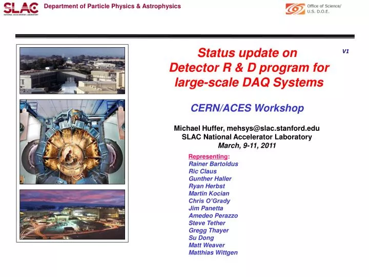
Status update on Detector R & D program for large-scale DAQ Systems CERN/ACES Workshop Michael Huffer, mehsys@slac.stanford.edu SLAC National Accelerator Laboratory March, 9-11, 2011. V1. Representing : Rainer Bartoldus Ric Claus Gunther Haller Ryan Herbst Martin Kocian

E N D
Status update on Detector R & D program for large-scale DAQ Systems CERN/ACES Workshop Michael Huffer, mehsys@slac.stanford.edu SLAC National Accelerator Laboratory March, 9-11, 2011 V1 Representing: Rainer Bartoldus Ric Claus Gunther Haller Ryan Herbst Martin Kocian Chris O’Grady Jim Panetta Amedeo Perazzo Steve Tether Gregg Thayer Su Dong Matt Weaver Matthias Wittgen
R & D program’s goals and phases • DAQ/trigger “technology” for next generation HEP experiments… • One component of ongoing SLAC Detector R & D project • “Phase 0” • “Survey the requirements and capture their commonality” • Intended to leverage recent industry innovation • Project’s cultural bias, “one size does not fit all”. Leads to… • The concept of ubiquitous building blocks • The (Reconfigurable) Cluster Element (RCE) • The ClusterInterconnect (CI) • Industry standard packaging (ATCA) • “Phase 1” • Technology evaluation & demonstration hardware • The RCE & CI boards • “Phase 2” • Useful, sustainable architecture (how to future proof) • Generic ATCA Front-Board (the COB) & the RCE “GEN-II” • “Phase 3” • Meet all RCE related performance goals • Move to ASP (ARM based silicon) This is where the program is currently executing
Outline • Brief recap of both ongoing and past ATLAS related activities • (Re) Introduce the RCE/CE + CI/Cluster • Status of “Phase-2” activities (the COB) • ATLAS upgrade related activities • IBL Read/Out (R/O) • Full pixel R/O system replacement • CSC ROD replacement • Forward Muon Readout (small wheel replacement) • Case studies on alternative architectures • Integration of ROD + ROS functionality • Level 1.5 triggers • ROIB • Summary Will focus only on the IBL as one, representative, example of these activities
Past & current ATLAS related activities • Presentations: • Mike Huffer at ACES (Mar/09 & sessions of last ATUW): • http://indico.cern.ch/materialDisplay.py?contribId=51&sessionId=25&materialId=slides&confId=47853 • Rainer Bartoldus at ROD workshop (June/09): • http://indico.cern.ch/materialDisplay.py?contribId=16&sessionId=4&materialId=slides&confId=59209 • RCE training workshop at CERN (June/09): • http://indico.cern.ch/conferenceOtherViews.py?view=standard&confId=57836 • Test-stands • Shared RCE test stand at CERN (August/09) • Stony Brook and LBNL (October/2010) • Pixel lab @CERN (February/2010) • Expressions of Interest • IBL (September/2009) • R/O systems for Full Pixel Replacement (December/2010) • R/O systems for the small wheel upgrade (December/2010) • DOE Collider Detector R & D LOI (Feburary/2011) • Pixel calibration system • 3D sensor test CERN test-beam (June 2010) • Calibration of FE-I4 (Decemeber/2010)
Existing Pixel Module or IBL FE-I4 module 3 Gb/s /CIM 10-GE Ethernet HSIO Application of RCE to ATLAS Pixel Typical test stand • Other applications: • Successful integration with EUDET @ CERN test beam. • Preparation of IBL stave-0 (16 x FE-I4) readout/calibration tests for Jun/Jul 2011. Cosmic Telescope @SLAC
Application of RCE to ATLAS Pixel Example of FE-I4 module tests using cosmic telescope data collected with RCE Hit time Crude alignment TOT Hit – track residual (mm)
Application of RCE to ATLAS Pixel • Standard Atlas pixel calibration console interface as used for Point-1. • Running ATLAS TDAQ inter-process communication software on RCE under RTEMS • Full suite of pixel calibration DSP code adopted to run on RCEs with < 1 FTE*year effort. RCE concept with integrated software support has demonstrated flexibility for compatibility and fast progress. Threshold calibration for an existing FE-I3 module with known defects
The RCE • Based on SOC technology… • Xilinx Virtex-5 & ASP • Has three principal components: • ProgrammableFabric • Paired with configuration flash • Both soft & hard silicon (resources) • ProgrammableCluster-Element (CE) • Paired with configuration flash • RAM (DDR2/DDR3), up to 4 Gbytes • Plugins • “Glues” fabric resources to CE • Itself is built from fabric resources • Comes bundled with two prebuilt: • Network (1-40Gb/sec Ethernet) • Interface to CE flash • CE has eight (8) sockets • 2 prewired to bundled plugins • 6 are application defined • Two most “interesting”, hardened resources: • DSP tiles (> 200 TeraMACS/Sec) • SerDes (+ support) (up to 12.5 Gbits/s)
The CE (hardware) • Processor (multiple cores) • Up to 5000 DMIPS (somewhere between Core Duo and i7) • Code + data stored on configuration media • Cross-bar • Provides “glue” between processor, memory & plugins • > 8 Gbytes/sec of switching bandwidth • P (Peripheral)-Bus • In concert with BSI and bootstrap provides “plug and play” support for plugins • C (Command)-Bus • Allows processor interaction with plugin concurrent with its memory transfers • Extends the processor’s instruction set • Provision for user to plugin its own application specific logic • Boot-Strap-Interface (BSI) • I2C slave interface • Allows external control & parameterization of boot process • House-Keeping-Interface (HKI) • I2C master interface • Allows external, configuration, control & monitoring of “slow” devices
The CE (software) (6 layer stack) • Primary Bootstrap • Operating System (O/S) agnostic • Driven by BSI • Operating System (O/S) + BSP • Bundled with Open Source R/T kernel (RTEMS) • POSIX compliant interfaces • Core • CE initialization • Plugin support • Utilities • Plugins • Driven by the set of physical plugins present • Well-Known-Services (WKS) • Standard BSD Network (IP) stack • Telenet, GDB stub, NFS, etc… • Set is customizable • Standard GNU cross-development environment • Includes remote (GDB) debugger • All software is object-oriented • Both C & C++ support
The CI & the related concept of Cluster • The CI consists of… • 96 channel 10G-Ethernet switch: • Partitioned into 24 ports of 4 channels each • Each port can be configured as: • 1-4 10G (KR) • 1 40G (KR4) • 1 4 x 3.125G (XAUI) • 1 SGMII (10, 100, 1000 Base-T) • Cut through, industry lowest (200-300 NS hop latency) • Full Layer 2 and Layer-3 switching • One (1) RCE • Manages switch (supports all management protocol) • Has fixed connection to one (1) port of the switch • The Cluster consists of… • One (1) CI • One or more (up to 96) RCE’s
“Phase 2”, Cluster-On-Board (COB) • “Mezzaninize” RCE & CI concepts • Decouples RCE & CI from ATCA (or any packaging standard) • New ATCA Front-Board which supports: • The mezzanine concept • Decouples Front-Board from RCE & CI • The cluster concept • IPMI (shelf configuration & monitoring) • Full mesh backplanes • Applications require only a single type of board • Interoperability with any type of backplane • The ATCA for physics standard (PICMG 3.8) • Complete interoperability with any type of ATCA board • 10 Gbits/s signaling (both backplanes & Ethernet switching) • Generic, synchronous Timing & Trigger signal distribution
COB block diagram • Partitioned into five zones (each with an associated mezzanine card) • Four (4) Data Processing Modules (DPM) • Process data from RTM • Intended to contain as many as eight (8) RCEs • One (1) Data Transport Module (DTM) • Distributes 10-GE Ethernet Fabric and timing signals to DPMs • Contains CI • Unlike DPM mezzanine extends to Front-Panel • IPM controller to monitor and configure the five zones + RTM
COB (Board layout and Front-Panel) DPM0 DPM1 Zone 3 PICMG 3.8 DPM3 DPM2 P2 switch TTC interface DTM “Busy” interface DC-DC Conversion/filter P1 IPMC
IBL R/O reusing current RODs • 4 crates • 8 fiber inputs/ROD (56 RODs) • Calibration information must flow through VME bus & RCC • No explicit provision for FTK
IBL R/O proposal based the COB… • Interfaces remain identical (TTC & ROS) • 1 crate (shelf) 12 COBs • 48 fiber inputs/COB (10 COBs) • Calibration data has independent, 160 gigabits/sec (Ethernet) path • Adding one more COB + SLINK/RTM easily accommodates FTK access
SLINKRTM SFP+ (1 of 8) Avago 12 channel receiver & transmitter (2 of 8)
Summary • Phase I of the program is complete • Working prototypes (the CI and CIM boards) deployed in real experiments • Phase II is well underway with the COB board & RCE “GEN-II” • All ATLAS upgrade activities based on this board. Its mezzanine boards… • Will have 8 RCEs and support 48 channels of generic serial I/O • Support the current Trigger Timing & Control (TTC) system & “busy” • GEN-I has demonstrated that the RCE is a viable software platform • Successful port of pixel calibration software • Operation as cosmic telescope using real FEE hardware (the FE-I4) • Proposed new R/O system for the IBL is based on the COB • Will integrate (plug into) into the present TDAQ structure • Much smaller footprint (4 crates -> 1 shelf) • Has two purpose built RTMs (SLINK & R/O) • Capable of transferring the entire calibration data volume at L1 rates • Designed to easily accommodate the FTK