Download
1 / 15
180 likes | 410 Vues
System Concept and Process Layout for a Mirco-CHP Unit based on Low Temperature SOFC. Thomas Pfeifer 1 , Laura Nousch 1 , Wieland Beckert 1 , Dick Lieftink 2 , Stefano Modena 3 (1) Fraunhofer IKTS, (2) Hygear Fuel Cell Systems, (3) SOFCPower. 10th European SOFC Forum 2012

E N D
System Concept and Process Layout for a Mirco-CHP Unit based on Low Temperature SOFC Thomas Pfeifer1, Laura Nousch1, Wieland Beckert1, Dick Lieftink2, Stefano Modena3 (1) Fraunhofer IKTS, (2) Hygear Fuel Cell Systems, (3) SOFCPower 10th European SOFC Forum 2012 Lucerne, June 26 - 29, 2012
What is LOTUS?Low Temperature SOFC µ-CHP System • Project of FCH JU (Fuel Cells and Hydrogen Joint Undertaking) • 3 year project: January 2011- December 2013 • Objectives: • CHP system at reduced stack-temperature of 650°C based on ASC technology • low cost, mass-produced and proven components • high electrical efficiency (min. 45%) and high total system efficiency • appropriate solutions for real-world operation
LOTUS Design Studies0-D Stack-Model Parameterization (sofc.dll) • U/I-Measurements at varying temperature and fuel-input provided by SOFCPower. • Model parameters identified by least squares fit of area specific cell resistance.
Expected Development:ASC700+20%66 x 80 cm², CH4-SR Reformate LOTUS Design StudiesStack Performance Estimation at 650 °C SOFCPower ASC700+20% enables LOTUS-development • Available Cell Technology:ASC70066 x 50 cm², CH4-SR Reformate 650 WDC @ 70% FU UCell = 0.7 V 1550 WDC @ 70% FU UCell = 0.7 V
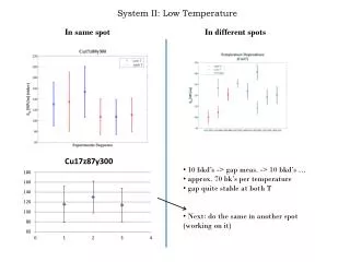
LOTUS Stack DevelopmentRecent Test-Results by SOFC Power • short-stack performance improvement is demonstrated under H2/N2 mixture 700°C 650°C
LOTUS Design StudiesEvaluation of Fuel Reforming Options • Stack-Internal Reforming (IR) • Pre-Reforming IR-SOFC Fuel H2O Fuel POX SOFC 800 °C 650 °C Steam Refor- ming (SR) Air Heat POX ATR Fuel Fuel ATR SR SOFC SOFC ATR Autothermal Reforming (ATR) H2O H2O POX Air Heat Partial Oxi- dation (POX) SR SR
LOTUS Design StudiesBoundary Conditions for the LOTUS System Design • stack temperature predetermines reforming temperature 650 °C • soot-free reformer operation requires S/C ~ 2 .. 3 • in practical µCHP-operation a lower system S/C is essential • controlled stack-internal reforming (IR) is beneficial for system efficiency • for start-up and shut-down of ASC a reducing atmosphere > 300 °C is required • part load operation and independent control of power to heat ratio is beneficial for system economics • LOTUS system design is governed • by the fuel reforming concept and its process integration
~ Electricity = SB - Start-up Burner FBP Fuel Bypass SR SOFC Stack Steam Reformer AB After- burner Fuel APH Air Pre-Heater Air EVP Water Evaporator CHP-Hx Heat Heat Exchanger Exhaust LOTUS System DesignProcess Flow Diagram (PFD) • Implementation of the LOTUS Fuel Reforming Concept • fuel bypass (FBP) for controlled stack-internal reforming • downscaled steam reformer (SR) • SR directly heated by burner exhaust (AB or SB) • optional use of oxidative steam reforming
LOTUS Component DevelopmentSteam Reformer Pre-Test supports coated with reformer catalyst reformer test rig …
LOTUS Component DevelopmentBurner Pre-Test test-rig and model of dual-use burner control panel for testing of the dual-use burner prototype
LOTUS Component DevelopmentBlower Development two stage high pressure blower with EC motor- prototype CFD simulation of the two stage high pressure blower
Thanks for your attention! www.lotus-project.eu