Download
1 / 21
210 likes | 338 Vues
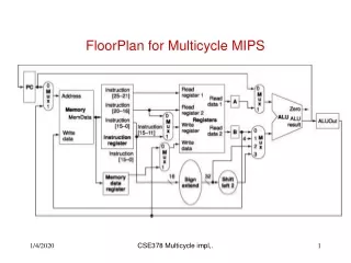
Redesign control FSM of a multicycle MIPS processor with low power state encoding. Introduction. Mealy and Moore FSMs. Introduction. MultiCycle MIPS controller is actually a moore FSM. 0000 (0). Fetch. 0001 (1). Decode. J. B. Exception. lw, sw. R. lw. 0010 (2). 0011 (3).

E N D
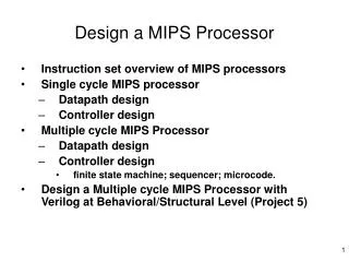
Redesign control FSM of a multicycle MIPS processor with low power state encoding
Introduction Mealy and Moore FSMs
Introduction MultiCycle MIPS controller is actually a moore FSM
0000 (0) Fetch 0001 (1) Decode J B Exception lw, sw R lw 0010 (2) 0011 (3) 0100 (4) 0101 (5) 0110 (6) 0111 (7) sw 1000 (8) 1001 (9) 1010 (10) Random Encoding 1 1 2 2 1 3 1 2 2 3 2 2 3 2 2 1
0000 (0) Fetch 0001 (1) Decode J B Exception lw, sw R lw 0111 (7) 0101 (5) 0011 (3) 1000 (8) 1001 (9) 1010 (10) sw 0110 (6) 0100 (4) 0010 (2) Optimized encoding 1 1 3 1 2 1 1 1 1 1 1 2 2 2 1 1
Encoding Algorithm Finding absolute optimal state encoding is NP hard, but there are some huristics: One Level Tree (OLT) [1] POW3 [2] Spanning Tree Based (STB) WCEC (Weakly Crossed Edge Cuts Ecoding) [1] Baccheta P., L. Daldoss, D. Sciuto and C. Silvano, “Lower- Power State Assignment Techniques for Finite State Machines”, IEEE International Symposium on Circuits and Systems (ISCAS’00), 2000, pp.II-641-II-644. [2] Benini L. and G. De Micheli, “State Assignment for Lower Power Dissipation”, IEEE Journal of Solid State Circuits, vol. 30, no 3, 1995, pp. 258-268.
Verilog code • States must be explicitly specified by the user. This can be done by explicitly using the bit pattern (e.g., 3’b101), or by defining a parameter (e.g., parameter s3 3’b101) and using the parameter as the case item.
Ways to further reduce Power State duplication: Switching activity reduced from 1.27 to 1.17
0000 (0) 0001 (1) 0111 (7) 0101 (5) 0011 (3) 1101 (13) 1011 (11) 1000 (8) sw 0110 (6) 0100 (4) 0010 (2) 1001 (9) Duplicate Fetch (12 states) Fetch1 Decode 1 1 1 2 J Exception B lw, sw 2 2 R lw 1 1 1 1 1 1 1 Fetch2 1 1 2 1
0000 (0) Fetch 0001 (1) Decode J B Exception lw, sw R lw 0111 (7) 0101 (5) 0011 (3) 1000 (8) 1001 (9) 1010 (10) sw 0110 (6) 0100 (4) 0010 (2) 11 states
One Hot Encoding • E.g. 4 states need 4 flip flops. • Only one flop will be active ("hot") in a state. 1000 (8) 0001 (1) 0010 (2) 0100 (4)
Advantages Low power (since only one toggle when state changes) Simple decoding logic. (Greatly reduces the complexity of CL)Popular method is onehot. FPGA has lot of registers compared to CPLD. so onehot is more suitable for FPGA
0000 (0) Fetch 0001 (1) Decode J B Exception lw, sw R lw 0111 (7) 0101 (5) 0011 (3) 1000 (8) 1001 (9) 1010 (10) sw 0110 (6) 0100 (4) 0010 (2) Clock gating
Clock gating D Q Gating signal clk