Download
1 / 32
620 likes | 1.59k Vues
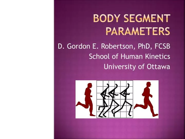
body segment parameters. D. Gordon E. Robertson, PhD, FCSB School of Human Kinetics University of Ottawa. body segment parameters Branch of anthropometry.

E N D
body segment parameters D. Gordon E. Robertson, PhD, FCSB School of Human Kinetics University of Ottawa
body segment parametersBranch of anthropometry • Necessary to derive kinetics from kinematics (I.e., Σ F = m a,Σ Mcg = Ia, a is acceleration of centre of gravity, a is ang. acceleration) • Called “inverse dynamics” • Need to compute: • segment mass • segment centre of gravity • segment moment of inertia tensor Biomechanics Lab, University of Ottawa
Segment Mass: • mass is a body’s resistance to changes in linear motion • need to measure total body mass using “balance scale” • each segment is a proportion of the total Biomechanics Lab, University of Ottawa
Segment Mass:e.g., thigh • Pthigh = mthigh / mtotal • Pthigh = thigh’s mass proportion • mtotal = total body mass • Therefore, mthigh = Pthighmtotal • Note, Σ Pi = 1 Biomechanics Lab, University of Ottawa
Centre of Gravity:definition • point at which a body can be balanced • (xcg, ycg, zcg)= centre of gravity • also called centre of mass • first moment of mass • i.e., turning effect on one side balances turning effect of other side of centre of mass Biomechanics Lab, University of Ottawa
Centre of Gravity:Empirical method: knife edge • balance body on a “knife edge” • balance along a different axis • intersection is centre of gravity Biomechanics Lab, University of Ottawa
Centre of Gravity:Empirical method: suspension • record plumb lines • intersection of plumb lines is centre Biomechanics Lab, University of Ottawa
Segment Centre of Gravity: Proportional method • Rp = rp / seg.length • rp= distance from centre of gravity to proximal end • need table of proportions derived from a population similar to subject • for many segments Rp is approximately 43% of segment length Biomechanics Lab, University of Ottawa
Table of proportions: dempster (modified) Biomechanics Lab, University of Ottawa
Segment Centre of Gravity: e.g., thigh • Rp = distance to c.of g. from proximal end as proportion of seg. length xcg = xp + Rp (xd – xp) ycg = yp + Rp (yd – yp) zcg = zp + Rp (zd – zp) • (xcg, ycg, zcg) = centre of gravity • (xp, yp, zp) = proximal end • (xd, yd, zd) = distal end Biomechanics Lab, University of Ottawa
Centre of Gravity:Limb or part of a body • weighted average of segment centres xlimb = S(Pi xi) ∕SPi ylimb = S(Piyi) ∕SPi zlimb = S(Pizi) ∕SPi • (xi, yi, zi) = mass centre of segment “i” • Pi = mass proportion of segment “i” • usually, SPi1 Biomechanics Lab, University of Ottawa
Centre of Gravity:Total Body • weighted sum of all segments’ centres xtotal = S(Pi xi) ytotal = S(Piyi) ztotal = S(Pizi) • (xtotal, ytotal , ztotal) = total body centre of gravity • note, SPi=1 Biomechanics Lab, University of Ottawa
moment of inertia:definition • body’s resistance to change in its angular motion • second moment of mass (squared distance) • of a point mass Ia = mr 2 • for a distributed mass Ia= r 2dm Biomechanics Lab, University of Ottawa
Moment of Inertia:Empirical method • Ia = mgrt2/ 4p2 • m = mass • r = radius of pendulum • g = 9.81m/s2 • t = period of oscillation (time 20 oscillations then ÷ 20) • oscillations must be less than ±5 degrees Biomechanics Lab, University of Ottawa
Parallel Axis Theorem:E.G., thigh about hip centre • rhip = distance from thigh centre of gravity to hip rhip = √[rx2 + ry2+ rz2] Ihip = Ithigh + mthigh rhip2 • Ithigh= moment of inertia about the thigh’s centre of mass • mthigh= segment mass Biomechanics Lab, University of Ottawa
Moment of Inertia:Limb or Total Body • repeated application of parallel axis theorem Itotal = ΣIi + Σ mi ri2 • Ii= segment moments of inertia about each segment’s centre of gravity • mi= segment masses • ri= distance of each segment’s centre to limb or total body centre of gravity Biomechanics Lab, University of Ottawa
geometric models:hanavan (1965) • Hanavan developed the first 3D model of the human for biomechanical analyses • model consisted of 15 segments of ten conical frusta, two spheroids, an ellipsoid, and two elliptical cylinders Biomechanics Lab, University of Ottawa
moment of inertia: geometric solids of uniform density • all models are assumed to be uniformly dense and symmetrical about their long axes • equations are based on integral calculus Biomechanics Lab, University of Ottawa
Newton-euler equations:Second law • Newton’s Second Law • SF = m a • For rotational motion of rigid bodies Euler extended this law to: where a = (ax, ay,az)T is the angular acceleration of the object about its centre of gravity and is the inertia tensor: Biomechanics Lab, University of Ottawa
moment of inertia in 3d:Inertia tensor • it can be shown that the inertia tensor can be reduced to a diagonal matrix for at least one specific axis • if body segments are modeled as symmetrical solids of revolution, using a local axis that places one axis (usually z) along the longitudinal axis of symmetry reduces the inertia tensor to: = Ixx, Iyy, Izzare called the principal moments of inertia Biomechanics Lab, University of Ottawa
moment of inertia:spheroid & ellipsoid • m = mass, r = radius Ixx = Iyy = Izz = 2/5 mr2 • a = depth (x), b = height (y), c = width (z) Ixx = 1/5 m (b2+c2) Iyy = 1/5 m (a2+c2) Izz = 1/5 m (a2+b2) Biomechanics Lab, University of Ottawa
moment of inertia:circular & elliptical cylinders • m = mass, l = length of cylinder, r = radius Ixx = 1/2 mr2 Iyy = 1/12 m (3r2+l2) Izz = 1/12 m (3r2+l2) • l = length, b = height/2 (y), c = width/2 (z) Ixx = 1/4 m (b2 +c2) Iyy = 1/12 m (3c2 +l2) Izz = 1/12 m (3b2 +l2) Biomechanics Lab, University of Ottawa
moment of inertia: right- circular cone and frustum • m = mass, l = length of cone, r = radius at base Ixx = 3/10 mr2 Iyy = 3/5 m (¼ r2 + l2) Izz= 3/5 m (¼ r2 + l2) • subtract smaller cone from larger Biomechanics Lab, University of Ottawa
visual3d uses geometric solidsE.G., fencing • for Visual3D tutorials visit: http://www.c-motion.com/v3dwiki/index.php?title=Tutorial_Typical_Processing_Session http://www.c-motion.com/v3dwiki/index.php?title=Tutorial:_Building_a_Model Biomechanics Lab, University of Ottawa
visual3d - models:creating the model • modeling begins by selecting a Vicon processed static trial • select Model| Create(Add Static Calibration File) • usually Hybrid Model from C3DFile is chosen Biomechanics Lab, University of Ottawa
visual3d - models:Select segment from menu • from Models tab select segment to be created • drop-down menu offers predefined segments • e.g., select Right Thigh Biomechanics Lab, University of Ottawa
visual3d - models:e.g., right thigh segment (rth) • define proximal lateral marker and radius of thigh • define distal lateral and medial markers • check all tracking markers for thigh or • or check box marked Use Calibration Targets for Tracking Biomechanics Lab, University of Ottawa
visual3d – models:segment properties • segment mass is 0.1000 × total body mass (default) • geometry is CONE (actually conical frustum) • computed principal moments of inertia are shown in kg.m2 • centre of mass’s axial location (metres) is based on thigh’s computed length Biomechanics Lab, University of Ottawa
visual3d – models: completed whole body • local 3D axes are shown at the proximal joint centres • yellow lines join segment endpoints • added epee “segment” Biomechanics Lab, University of Ottawa
visual3d – models: completed whole body • skeletal “skin” Biomechanics Lab, University of Ottawa
Examples:ground level plates lacrosse gymnastics lifting ballet Biomechanics Lab, University of Ottawa
Examples:special force plates seat and grabrail stairs rowing obstacle Biomechanics Lab, University of Ottawa