Download
1 / 55
560 likes | 590 Vues
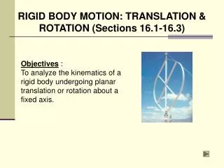
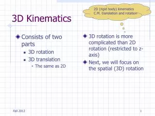
Chapter 20: 3-D Kinematics of a Rigid Body. Chapter Objectives. • To analyze the kinematics of a body subjected to rotation about a fixed axis and general plane motion. • To provide a relative-motion analysis of a rigid body using translating and rotating axes. Chapter Outline.

E N D
Chapter Objectives • To analyze the kinematics of a body subjected to rotation about a fixed axis and general plane motion. • To provide a relative-motion analysis of a rigid body using translating and rotating axes.
Chapter Outline • Rotation About a Fixed Point • The Time Derivative of a Vector Measured from • Either a Fixed or Translating- Rotating System • General Motion • Relative-Motion Analysis Using Translating and • Rotating Axes
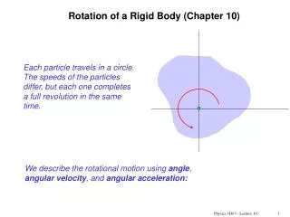
Rotational About a Fixed Point • When a rigid body rotates about a fixed point, the distance r from the point to a particle P located on the body is the same for any position of the body • Thus, the path of motion for the particle lines on the surface of a sphere having a radius r and centered at the fixed point • Since motion along this path occurs only from a series of rotations made during a finite time interval, we will first develop a familiarity with some of the properties of rotational displacements
Rotational About a Fixed Point Euler’s Theorem • Euler’s Theorem states that two “component” rotations about different axes passing through a point are equivalent to a single resultant rotation about an axis passing through the point • If more than two rotations are applied, they can be combined into pairs, and each pair can be further reduced to combine into one rotation.
Rotational About a Fixed Point Finite Rotations • if component rotations used in Euler’s theorem are finite, it is important that the order in which they are applied be maintained • This is because finite rotations do not obey the law of vector addition, and hence they cannot be classified as vector quantities
Rotational About a Fixed Point • Consider the 2 finite rotations θ1 + θ2 applied to block. Each rotation has a magnitude of 90° and a direction defined by the right-hand rule, as indicated by the arrow • The resultant orientation of the block is shown at the right
Rotational About a Fixed Point • When these two rotations are applied in the order θ2 + θ1 ,as shown, the resultant position of the block is not the same as in the previous diagram
Rotational About a Fixed Point • Consequently, finite rotations do not obey the commutative law of addition (θ1 + θ2 ≠ θ2 + θ1 ), and therefore they cannot be classified as vectors • If smaller, yet finite rotations had been used to illustrate this point, e.g., 10° instead of 90°, the resultant orientation of the block after each combination of rotations would also be different; however, in this case, the difference is only a small amount
Rotational About a Fixed Point Infinitesimal Rotations • When defining the angular motions of the body subjected to three-dimensional motion, only rotations which are infinitesimally small will be considered • Such rotations may be classified as vectors, since they can be added vectorially in any manner
Rotational About a Fixed Point • Consider the rigid body itself to be a sphere which is allowed to rotate about its central fixed point O • If we impose two infinitesimal rotations dθ1 + dθ2 on the body, it is seen that point P moves along the path dθ1 x r + dθ2 x r and ends up at P’
Rotational About a Fixed Point • Had the two successive rotations occurred in the order dθ2 + dθ1, then the resultant displacements of P would have been dθ2 x r + dθ1 x r • Since the vector cross product obeys the distributive law, by comparison (dθ1 + dθ2) x r = (dθ2 + dθ1) x r
Rotational About a Fixed Point • Here infinitesimal rotations dθ are vectors, since these quantities have both a magnitude and direction for which the order of (vector) addition is not important, i.e., dθ1 + dθ2 = dθ2 + dθ1 • Furthermore, the two “component” rotations dθ1 + dθ2 are equivalent to a single resultant rotation dθ=dθ1 + dθ2 , a consequence of Euler’s theorem
Rotational About a Fixed Point Angular Velocity • If the body is subjected to an angular rotation dθ about a fixed point, the angular velocity of the body is defined by the time derivative, • The line specifying the direction of ω, which is collinear with dθ is referred to as the instantaneous axis of rotation
Rotational About a Fixed Point • In general, this axis changes direction during each instant of time • Since dθ is a vector quantity, so too is ω, and it follows from vector addition that if the body is subjected to two component angular motions, and • The resultant angular velocity is ω = ω1 + ω2
Rotational About a Fixed Point Angular Acceleration • The body’s angular acceleration is determined from time derivative of angular velocity, • For motion about a fixed point, α must account for a change in both the magnitude and direction of ω, so that, in general, α is not directed along the instantaneous axis of rotation.
Rotational About a Fixed Point • As the direction of the instantaneous axis of rotation (or the line of action of ω) changes in space, the locus of points defined by the axis generates a fixed space cone.
Rotational About a Fixed Point • If the change in this axis is viewed with respect to the rotating body, the locus of the axis generates a body cone • At any given instant, these cones are tangent along the instantaneous axis of rotation, and when the body is in motion, the body cone appears to roll either on the inside or the outside surface of the fixed space cone
Rotational About a Fixed Point • Provided the paths defined by the open ends of the cones are described by the head of the ωvector,αmust act tangent to these paths at any given instant, since the time rate of change ofωis equal toα
Rotational About a Fixed Point Velocity • Once ω is specified, the velocity of any point P on a body rotating about a fixed point can be determined using the same methods for a body rotating about a fixed axis • Hence, by cross product, • r defines the position of P measure from the fixed point O
Rotational About a Fixed Point Acceleration • If ω and α are known at a given instant, the acceleration of any point P on the body can be obtained by time differentiation of previous equation, which yields, • The equation defines the acceleration of a point located on a body subjected to rotation about a fixed axis
The Time Derivative of a Vector Measured From Either a Fixed or Translating-Rotating System • In many types of problems involving the motion of the body about a fixed point, the angular velocity ω is specified in terms of its component angular motions • For example, the disk as shown spins about the horizontal y axis at ωs while it rotates or precesses about the vertical z axis at ωp
The Time Derivative of a Vector Measured From Either a Fixed or Translating-Rotating System • Therefore its resultant angular velocity is ω = ωs + ωp • If the angular acceleration α = ω of such a body is to be determined, it is sometimes easier to compute the time derivative of ωby using a coordinate system which has a rotation defined by one or more of the components of ω .
The Time Derivative of a Vector Measured From Either a Fixed or Translating-Rotating System • For this reason, and for other uses later, an equation will presently be derived that relates the time derivative of any vector A defined from a translating-rotating reference to its time derivative defined from a fixed reference.
The Time Derivative of a Vector Measured From Either a Fixed or Translating-Rotating System • Consider the x, y, z axes of the moving frame reference to have an angular velocity Ω which is measured from the fixed X, Y, Z axes • It will be convenient to express vector A in terms of its i, j, k components, which defined the directions of the moving axes
The Time Derivative of a Vector Measured From Either a Fixed or Translating-Rotating System • Hence, • The time derivative of A must account for the change in both the vector’s magnitude and direction • However, if this derivative is taken with respect to the moving frame of reference, only a change in the magnitudes of the components of A must be accounted for
The Time Derivative of a Vector Measured From Either a Fixed or Translating-Rotating System • Since the directions of the components do not change with respect to the moving reference. Hence, • When the time derivative of A is taken with respect to the fixed frame of reference, the directions of i, j, k change only on account of the rotation, Ω, of the axes and not their translation
The Time Derivative of a Vector Measured From Either a Fixed or Translating-Rotating System • Hence in general, • i = di/dt represents only a change in the direction of i with respect to time, since i has a fixed magnitude of 1 unit • The change, di is tangent to the path as i moves due to the rotation Ω .
The Time Derivative of a Vector Measured From Either a Fixed or Translating-Rotating System • Accounting for both the magnitude and direction of di, we can define i using the cross product, i = Ω x i • Therefore we can obtain .
The Time Derivative of a Vector Measured From Either a Fixed or Translating-Rotating System • The equation states that the time derivative of any vectorA as observed from the fixed X, Y, Z frame of reference is equal to the time rate of change of A as observed from x, y, z translating-rotating frame of reference • Ω x A is the change of A caused by the rotation of the of the x, y, z frame • It should always be used whenever Ω produces a change in the direction of A as seen from the X, Y, Z reference
The Time Derivative of a Vector Measured From Either a Fixed or Translating-Rotating System • If this change does not occur, i.e., Ω = 0, then the time rate of change of A as observed from both coordinate system will be the same.
General Motion • In this section, a translating coordinate system will be used to define relative motion • Shown in figure is a rigid body subjected to general motion in three dimensions for which the angular velocity is ω and the angular acceleration is α
General Motion • If point A has a known motion of vA and aA, the motion of any other point B may be determined by using this relative motion analysis • If the origin of the translating coordinate system x, y, z (Ω = 0) is located at the “base point” A, then, at the instant shown, the motion of the body may be regarded as the sum of an instantaneous translation of the body having a motion of vA and aA and a rotation of body about an instantaneous axis passing through the base point
General Motion • Since the body is rigid, the motion of point B measured by an observer located at A is the same as motion of the body about a fixed point. • This relative motion occurs about the instantaneous axis of rotation is defined by vB/A = ω x rB/A , aB/A = α x rB/A + ω x (ω x rB/A) • For translating axes the relative motions are related to absolute motions by vB = vA + vB/A and aB = aA + aB/A so that the absolute velocity and acceleration of point B can be determined from
General Motion and • These two equations are identical to those describing the general plane motion of a rigid body
General Motion • However, there will be difficulty in application for three-dimensional motion, because α measures the change in both the magnitude and direction of ω • This is because for general plane motion, α and ω are always parallel or perpendicular to the plane of motion, and therefore α measures only a change in the magnitude of ω
Relative-Motion Analysis Using Translation and Rotating Axes • The locations of points A and B are specified relative to the X, Y, and Z frame of reference by position vectors rA and rB. • The base point A represents the origin of the x, y, z coordinate system, which is translating and rotating with respect to X, Y, Z
Relative-Motion Analysis Using Translation and Rotating Axes • At the instant considered, the velocity and acceleration of point A are vA and aA, respectively, and the angular velocity and angular acceleration of the x, y, z axes are Ω and Ω = dΩ/dt, respectively • All these vectors are measured w.r.t the X, Y, Z frame of reference, although they may be expressed in Cartesian component form along either set of axes. .
Relative-Motion Analysis Using Translation and Rotating Axes Position • If the position of “B w.r.t A” is specified by the relative-position vector rB/A, then by vector addition,
Relative-Motion Analysis Using Translation and Rotating Axes Velocity • The velocity of point B measured from X, Y, Z is determined by taking the time derivative of relative position equation, • rB/A is measured between two points in a rotating reference. Hence,
Relative-Motion Analysis Using Translation and Rotating Axes • Here (vB/A)xyz is the relative velocity of B w.r.t A measured from x, y, z. Thus,
Relative-Motion Analysis Using Translation and Rotating Axes Acceleration • The acceleration of point B measured from X, Y, Z is determined by taking time derivative of relative velocity equation, which yields, • Where
Relative-Motion Analysis Using Translation and Rotating Axes • Here (aB/A)xyz is the relative acceleration of B w.r.t A measured from x, y, z. Thus,
PROCEDURE FOR ANALYSIS Coordinate Axes • Select the location and orientation of the X, Y, Z and x, y, z coordinate axes • Most often solutions are easily obtained if at the instant considered: 1) The origins are coincident 2) The axes are collinear 3) The axes are parallel
PROCEDURE FOR ANALYSIS • If several components of angular velocity are involved in a problem, the calculations will be reduced if the x, y, z axes are selected such that only one component of angular velocity is observed in this frame (Ωxyz) and the frame rotates with Ω defined by the other components of angular velocity
PROCEDURE FOR ANALYSIS Kinematics Equations • After the origin of the moving reference, A, is defined and the moving point B is specified, the equations should be written in symbolic form as
PROCEDURE FOR ANALYSIS • If rA and Ω appear to change direction when observed from the fixed X, Y, Z reference use a set of primed reference axes, x’, y’, z’ having Ω’ = Ω and to determine Ωxyz and the relative motion (vB/A)xyz and (aB/A)xyz • After the final form of Ω, vA, aA, Ωxyz, (vB/A)xyz and (aB/A)xyzare obtained, numerical problem data may be substituted and the kinematic terms evaluated . . .
PROCEDURE FOR ANALYSIS • The components of all these vectors may be selected either along the X, Y, Z axes or along x, y, z. The choice is arbitrary, provided a consistent set of unit vectors is used.
CHAPTER REVIEW Rotation About a Fixed Point • When a body rotates about a fixed point O, then points on the body follow a path that lies on the surface of a sphere • Infinitesimal rotations are vector quantities, whereas finite rotations are not • Since the angular acceleration is a time rate of change in the angular velocity, then we must account for both the magnitude and direction changes of ω when finding it derivative.
CHAPTER REVIEW • To do this, the angular velocity is often specified in terms of its component motions, such that some of these components will remain constant relative to rotating x, y, z axes • If this is the case, then the time derivative relative to the fixed axis can be determined, that is