Download
1 / 28
280 likes | 284 Vues
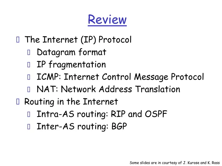
Review. The Internet (IP) Protocol Datagram format IP fragmentation ICMP: Internet Control Message Protocol NAT: Network Address Translation Routing in the Internet Intra-AS routing: RIP and OSPF Inter-AS routing: BGP. Some slides are in courtesy of J. Kurose and K. Ross.

E N D
Review • The Internet (IP) Protocol • Datagram format • IP fragmentation • ICMP: Internet Control Message Protocol • NAT: Network Address Translation • Routing in the Internet • Intra-AS routing: RIP and OSPF • Inter-AS routing: BGP Some slides are in courtesy of J. Kurose and K. Ross
IP protocol version number 32 bits total datagram length (bytes) header length (bytes) type of service head. len ver length for fragmentation/ reassembly fragment offset “type” of data flgs 16-bit identifier max number remaining hops (decremented at each router) upper layer time to live Internet checksum 32 bit source IP address 32 bit destination IP address upper layer protocol to deliver payload to E.g. timestamp, record route taken, specify list of routers to visit. Options (if any) data (variable length, typically a TCP or UDP segment) IP datagram format how much overhead with TCP? • 20 bytes of TCP • 20 bytes of IP • = 40 bytes + app layer overhead
Why different Intra- and Inter-AS routing ? Policy: • Inter-AS: admin wants control over how its traffic routed, who routes through its net. • Intra-AS: single admin, so no policy decisions needed Scale: • hierarchical routing saves table size, reduced update traffic Performance: • Intra-AS: can focus on performance • Inter-AS: policy may dominate over performance
Overview • Multicast Routing • Data Link Layer Services Some slides are in courtesy of J. Kurose and K. Ross
Multicast: act of sending datagram to multiple receivers with single “transmit” operation analogy: one teacher to many students Question: how to achieve multicast Multicast via unicast • source sends N unicast datagrams, one addressed to each of N receivers routers forward unicast datagrams multicast receiver (red) not a multicast receiver (red) Multicast: one sender to many receivers
Multicast: act of sending datagram to multiple receivers with single “transmit” operation analogy: one teacher to many students Question: how to achieve multicast Multicast: one sender to many receivers Network multicast • Router actively participate in multicast, making copies of packets as needed and forwarding towards multicast receivers Multicast routers (red) duplicate and forward multicast datagrams
Multicast: act of sending datagram to multiple receivers with single “transmit” operation analogy: one teacher to many students Question: how to achieve multicast Multicast: one sender to many receivers Application-layer multicast • end systems involved in multicast copy and forward unicast datagrams among themselves
Internet Multicast Service Model 128.59.16.12 multicast group concept: use of indirection • hosts addresses IP datagram to multicast group • routers forward multicast datagrams to hosts that have “joined” that multicast group 128.119.40.186 multicast group 226.17.30.197 128.34.108.63 128.34.108.60
Multicast groups • class D Internet addresses reserved for multicast: • host group semantics: • anyone can “join” (receive) multicast group • anyone can send to multicast group • no network-layer identification to hosts of members • needed: infrastructure to deliver mcast-addressed datagrams to all hosts that have joined that multicast group
Joining a mcast group: two-step process • local: host informs local mcast router of desire to join group: IGMP (Internet Group Management Protocol) • wide area: local router interacts with other routers to receive mcast datagram flow • many protocols (e.g., DVMRP, MOSPF, PIM) IGMP IGMP wide-area multicast routing IGMP
Source-based trees Multicast Routing: Problem Statement • Goal: find a tree (or trees) connecting routers having local mcast group members • tree: not all paths between routers used • source-based: different tree from each sender to rcvrs • shared-tree: same tree used by all group members Shared tree
Approaches for building mcast trees Approaches: • source-based tree: one tree per source • shortest path trees • reverse path forwarding • group-shared tree: group uses one tree • minimal spanning (Steiner) • center-based trees
1 i 5 4 3 6 2 Shortest Path Tree • mcast forwarding tree: tree of shortest path routes from source to all receivers • Dijkstra’s algorithm S: source LEGEND R1 R4 router with attached group member R2 router with no attached group member R5 link used for forwarding, i indicates order link added by algorithm R3 R7 R6
Reverse Path Forwarding if (mcast datagram received on incoming link on shortest path back to center) then flood datagram onto all outgoing links else ignore datagram • rely on router’s knowledge of unicast shortest path from it to sender • each router has simple forwarding behavior:
Reverse Path Forwarding: example S: source LEGEND R1 R4 router with attached group member R2 router with no attached group member R5 datagram will be forwarded R3 R7 R6 datagram will not be forwarded • result is a source-specific reverse SPT • may be a bad choice with asymmetric links
Reverse Path Forwarding: pruning • forwarding tree contains subtrees with no mcast group members • no need to forward datagrams down subtree • “prune” msgs sent upstream by router with no downstream group members LEGEND S: source R1 router with attached group member R4 router with no attached group member R2 P P R5 prune message links with multicast forwarding P R3 R7 R6
Shared-Tree: Steiner Tree • Steiner Tree: minimum cost tree connecting all routers with attached group members • problem is NP-complete • excellent heuristics exists • not used in practice: • computational complexity • information about entire network needed • monolithic: rerun whenever a router needs to join/leave
Center-based trees • single delivery tree shared by all • one router identified as “center” of tree • to join: • edge router sends unicast join-msg addressed to center router • join-msg “processed” by intermediate routers and forwarded towards center • join-msg either hits existing tree branch for this center, or arrives at center • path taken by join-msg becomes new branch of tree for this router
Center-based trees: an example Suppose R6 chosen as center: LEGEND R1 router with attached group member R4 3 router with no attached group member R2 2 1 R5 path order in which join messages generated R3 1 R7 R6
Overview • Multicast Routing • Data Link Layer Services Some slides are in courtesy of J. Kurose and K. Ross
Some terminology: hosts and routers are nodes (bridges and switches too) communication channels that connect adjacent nodes along communication path are links wired links wireless links LANs Data unit is a frame,encapsulates datagram “link” Link Layer: Introduction data-link layer has responsibility of transferring datagram from one node to adjacent node over a link
M M H H H H H H H H H H H H t t t t l n l t n n t n M M M M application transport network link physical application transport network link physical M M Protocol layering and data Each layer takes data from above • adds header information to create new data unit • passes new data unit to layer below source destination message segment datagram frame
Datagram transferred by different link protocols over different links: e.g., Ethernet on first link, frame relay on intermediate links, 802.11 on last link Each link protocol provides different services e.g., may or may not provide rdt over link transportation analogy trip from New York to Lausanne limo: New York to JFK plane: JFK to Geneva train: Geneva to Lausanne Link layer: context
Link Layer Services • Framing, link access: • encapsulate datagram into frame, adding header, trailer • channel access if shared medium • ‘physical addresses’ used in frame headers to identify source, dest • different from IP address! • Error Detection: • errors caused by signal attenuation, noise. • receiver detects presence of errors: • signals sender for retransmission or drops frame • Error Correction: • receiver identifies and corrects bit error(s) without resorting to retransmission • Half-duplex and full-duplex • with half duplex, nodes at both ends of link can transmit, but not at same time
link layer implemented in “adaptor” (aka NIC) Ethernet card, PCMCI card, 802.11 card sending side: encapsulates datagram in a frame adds error checking bits, rdt, flow control, etc. receiving side looks for errors, rdt, flow control, etc extracts datagram, passes to rcving node frame frame Adaptors Communicating datagram rcving node link layer protocol sending node adapter adapter
Error Detection • EDC= Error Detection and Correction bits (redundancy) • D = Data protected by error checking, may include header fields • Error detection not 100% reliable! • protocol may miss some errors, but rarely • larger EDC field yields better detection and correction
Parity Checking Two Dimensional Bit Parity: Detect and correct single bit errors Single Bit Parity: Detect single bit errors • Odd parity • Even parity 0 0
Sender: treat segment contents as sequence of 16-bit integers checksum: addition (1’s complement sum) of segment contents sender puts checksum value into UDP checksum field Receiver: compute checksum of received segment check if computed checksum equals checksum field value: NO - error detected YES - no error detected. But maybe errors nonetheless? More later …. Internet checksum Goal: detect “errors” (e.g., flipped bits) in transmitted segment (note: used at transport layer only)